500-8067.9 • INSTALLATION AND OPERATING INSTRUCTIONS • 8DJH • Revision 05 23/121
Description
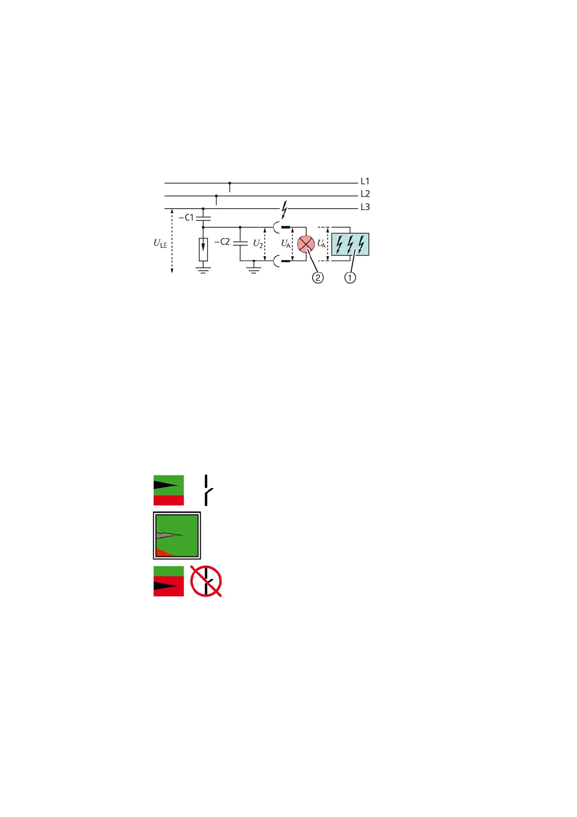
7.9 Voltage detecting systems
For voltage detection according to IEC 61243-5 and VDE 0682 Part 415 with the following
voltage detecting systems:
• Plug-in HR or LRM voltage indicator
• Integrated voltage indicators:
-VOIS
-CAPDIS
-WEGA
• -C1: Capacitance integrated into bushing
• -C2: Capacitance of the connection leads and the voltage indicator to earth
•U
LE
= U
N
/√3 during rated operation in the three-phase system
•U
2
= U
A
= Voltage at the interface (plug-in sockets) of the plug-in voltage indicator or the
test socket of the integrated voltage indicator
7.10 Ready-for-service indicator
The switchgear vessels are filled with insulating gas and are under pressure. The ready-for-
service indicator at the operating front of the panel shows if the gas density in the gas-
insulated switchgear vessel is in order.
Fig. 17: Ready-for-service indicator
Features • Self-monitoring, easy to read
• Independent of temperature and external pressure variations
• Independent of the site altitude
• Only responds to changes in gas density
• Option: Signaling switch 1°changeover contact for remote electrical indication
Fig. 16: Voltage detecting system via capacitive voltage
divider (principle)
①
Integrated voltage indicator
②
Plug-in HR or LRM voltage
indicator

 Loading...


