Installation
72/121 Revision 05 • INSTALLATION AND OPERATING INSTRUCTIONS • 8DJH • 500-8067.9
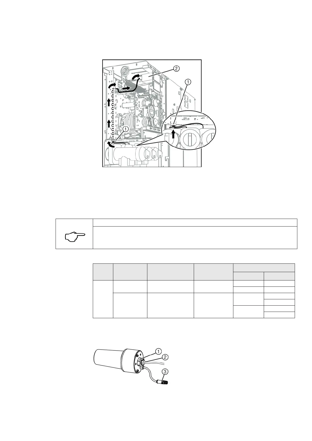
Laying the connection
cables
➭ If they have not been pre-assembled at the factory, lead the connection cables of the
ring-core current sensors through the cable tube ① upwards into the low-voltage
compartment or the operating mechanism compartment. Connect the connection cables to
the secondary devices ② according to the circuit diagram.
✔ The installation of the ring-core current sensors is completed.
13.5 Installing voltage sensors
Voltage sensors are mounted on the cable plug instead of the sealing stopper during cable
installation.
Voltage sensors and cable plugs for use
①
Cable tube
②
Secondary device
NOTE
➭ Observe the installation instructions of the voltage sensor manufacturer.
Make Type Description Insulation level
U [kV]
Cable plug
Make Type
Zelisko SMVS-UW1001 Voltage sensor for cone
according to EN 50180
24/50/125
1
Nexans (K) (M) 440TB
Cellpack CTS-S
SMVS-UW1002 Voltage sensor with
shortened cone
24/50/125
1
nkt cables CB-24
CC-24
TE Connectivity RSTI-58xx
RSTI-CC58xx
1
Rated voltage / rated power-frequency withstand voltage / lightning
impulse withstand voltage
Fig. 47: Voltage sensor (example)
①
Cast-resin hexagon (key size 24)
Tightening torque: 30 Nm max.
②
Connection of earthing cable
Conductor cross-section: min. 6 mm
2
Tightening torque: 6 Nm max.
③
Plug connection of the measuring lead

 Loading...


