Operation
108/121 Revision 05 • INSTALLATION AND OPERATING INSTRUCTIONS • 8DJH • 500-8067.9
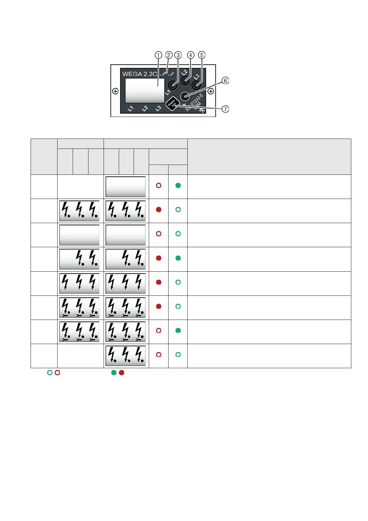
20.3 WEGA indications
Fig. 66: Operating elements WEGA
①
Display (illuminated for WEGA 2.2C if
auxiliary voltage is available)
②
LEDs green and red (state of the relay
contacts)
③
Test socket L1
④
Test socket L2
⑤
Test socket L3
⑥
Earth socket
⑦
"Display Test" button
Indication WEGA 1.2C WEGA 2.2C Description of the indication
L1 L2 L3 L1 L2 L3 State of the
relay contacts
1
Red Green
A0 U ≠ 0 U = 0 • Operating voltage not present.
A1 U ≠ 0 U = 0 • Operating voltage present.
• Integrated repeat test passed.
A2 U ≠ 0 U = 0 • Operating voltage not present.
A3 U ≠ 0 U = 0 • Failure of the operating voltage at phase L1
• Operating voltage present at phases L2 and L3.
• Integrated repeat test passed (L2 and L3).
A4 U ≠ 0 U = 0 • Voltage present, current monitoring of coupling section below limit
value.
A5 U ≠ 0 U = 0 If "Display Test" button is pressed:
• Display test passed.
A6 U ≠ 0 U = 0 In operation:
• Voltage present and integrated repeat test passed.
• Voltage signal too high.
A7 U ≠ 0 U = 0 • Auxiliary voltage missing.
1
LED does not light up, LED lights up

 Loading...


