Operation
106/121 Revision 05 • INSTALLATION AND OPERATING INSTRUCTIONS • 8DJH • 500-8067.9
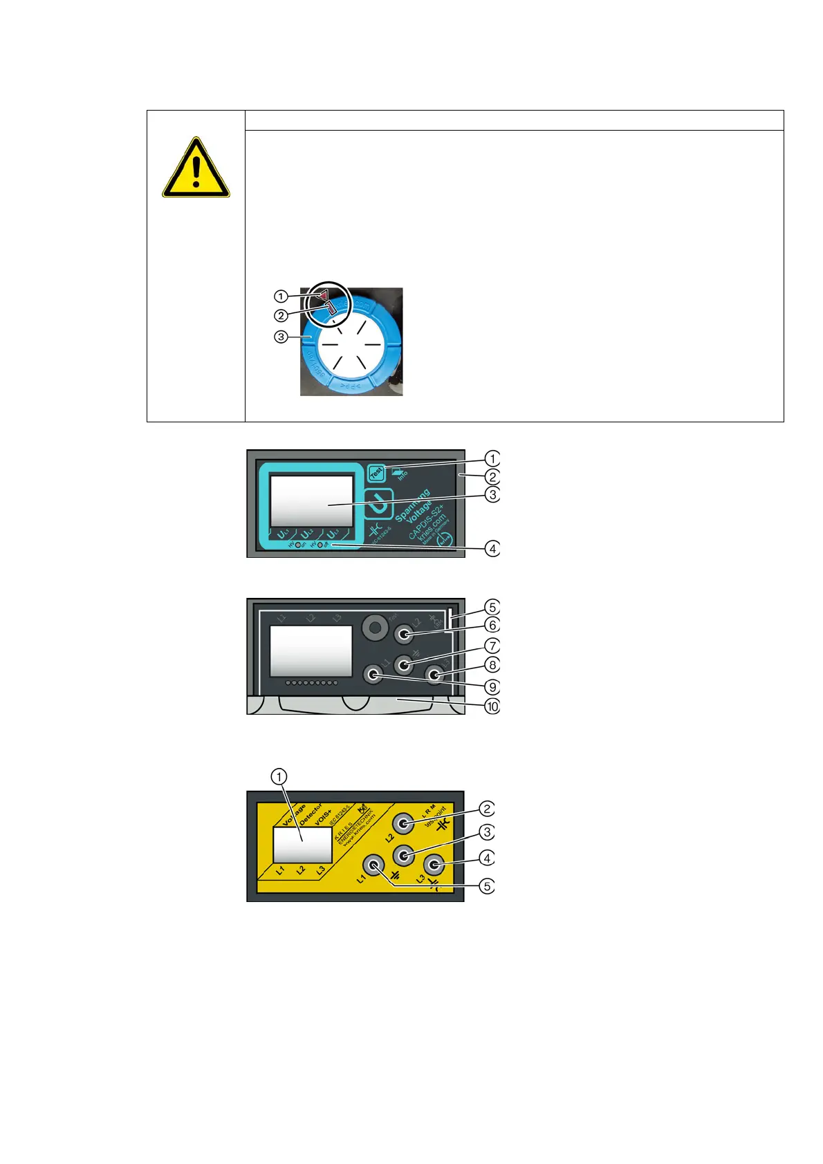
20.2 VOIS and CAPDIS indications
DANGER
High voltage! Danger! Do only modify the factory setting of the C2 module in the voltage
detecting system CAPDIS-S1+/S2+ after consultation with the regional Siemens representative!
➭ If the setting of the C2 module was modified by mistake, re-establish the factory setting as
follows:
- Pull out the C2 module
③ at the rear side of CAPDIS-S1+/S2+. Attention: Open printed
circuit board may be energized.
-Plug the C2 module
③ into CAPDIS-S1+/S2+ so that the marked arrow ① on the housing
points to the marking
② on the C2 module
Fig. 62: Marking of the factory setting on the C2 module
Fig. 63: CAPDIS-S2+: Cover closed
Fig. 64: CAPDIS-S2+: Cover opened
①
"Test" button
②
Cover
③
LC display
④
LEDs red and green (state of the
relay contacts)
⑤
Duct for signaling cables CAPDIS-M
⑥
Test socket L2
⑦
Earth socket
⑧
Test socket L3
⑨
Test socket L1
⑩
Short instructions
Fig. 65: VOIS+: Cover opened
①
LC display
②
Test socket L2
③
Earth socket
④
Test socket L3
⑤
Test socket L1

 Loading...


