500-8067.9 • INSTALLATION AND OPERATING INSTRUCTIONS • 8DJH • Revision 05 75/121
Installation
Availability of lateral wiring ducts in the cable compartment
The terminal strips of the secondary equipment supplied are assigned to the associated
operating mechanisms or feeders. For information about the external connection, see the
supplied circuit diagrams.
➭ Switch off auxiliary voltage.
➭ Remove the front plate.
➭ Connect the customer wiring ⑦ to the terminal strip ⑥ or directly to the equipment
terminals (e.g. CAPDIS S2+, short-circuit indicators) according to the circuit diagrams, and
lay it cleanly.
➭ If available, use the wiring duct ① on the operating mechanism box and the lateral wiring
ducts ② .
- Lead the secondary wires of the current transformers and voltage transformers through
steel mesh tubes or steel tubes in a shielded way into a lateral wiring duct.
- Earth the steel mesh tubes or steel tubes with metal cable straps.
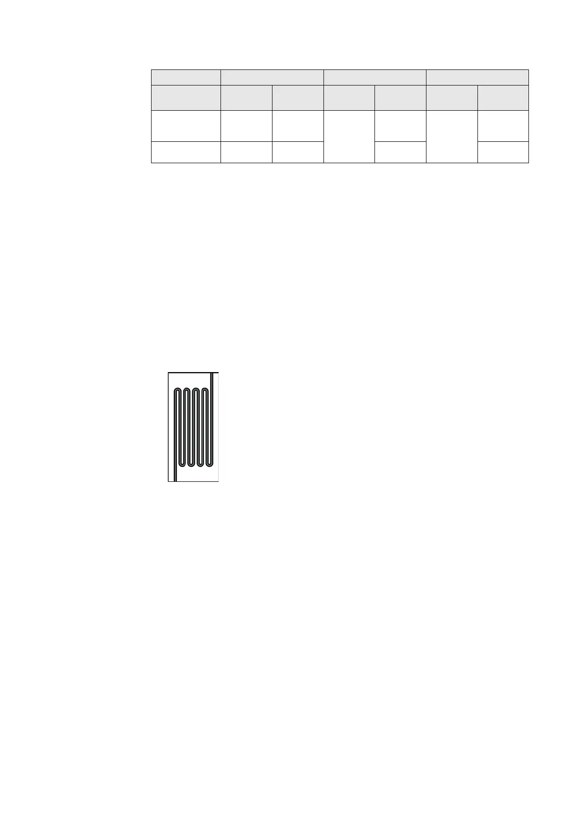
➭ Avoid extra-long secondary wires or lay them in the wiring ducts ① and ② or the fixing
duct ⑤ in a meandering pattern.
Fig. 52: Secondary wires laid in a meandering pattern
➭ Wire routing to the side is possible through the cut out cap ③ .
➭ For wire routing from below, use screened cable plugs.
➭ Do not switch on auxiliary voltage yet.
13.7 Correcting circuit diagrams
➭ Document any modification due to installation.
➭ Document the modifications in the circuit diagram.
➭ Send documented modifications to the regional Siemens representative.
Panel type R, K T L
Lateral wiring
duct
left right left right left right
Panel without
current
transformers
on request on request
partially
occupied
yes
yes
yes
Panel with current
transformers
on request partially
occupied
partially
occupied
partially
occupied

 Loading...


