Installation
54/121 Revision 05 • INSTALLATION AND OPERATING INSTRUCTIONS • 8DJH • 500-8067.9
12.6 Preparing the switchgear room
Switchgear installation Possible switchgear installations:
• Wall-standing arrangement
• Free-standing arrangement (option)
Switchgear dimensions For switchgear dimensions, see page 59, "Floor openings and fixing points" or the order
documents (dimension drawings, front views).
Pressure relief In the standard design, the pressure is relieved downwards. For further information, see page
22, "Possibilities for pressure relief".
Room dimensions The room dimensions result from the total width of the switchgear and the required wall
distances.
Room heights The minimum room height required results from the height of the switchgear and possible
top-mounted units, such as a low-voltage compartment or wiring duct.
Door dimensions The door dimensions depend on the
- Number of panels in a transport unit
- Design with or without low-voltage compartment
Weights For data, see page 34, "Dimensions and weights".
ATTENTION
Please observe the following for room planning and switchgear installation:
➭ The dimensions of the floor openings must be according to the dimension drawing in the
switchgear documentation.
➭ The height of the cable basement must at least correspond to the cable bending radius.
➭ The pressure relief rooms must be according to the dimension drawing in the switchgear
documentation.
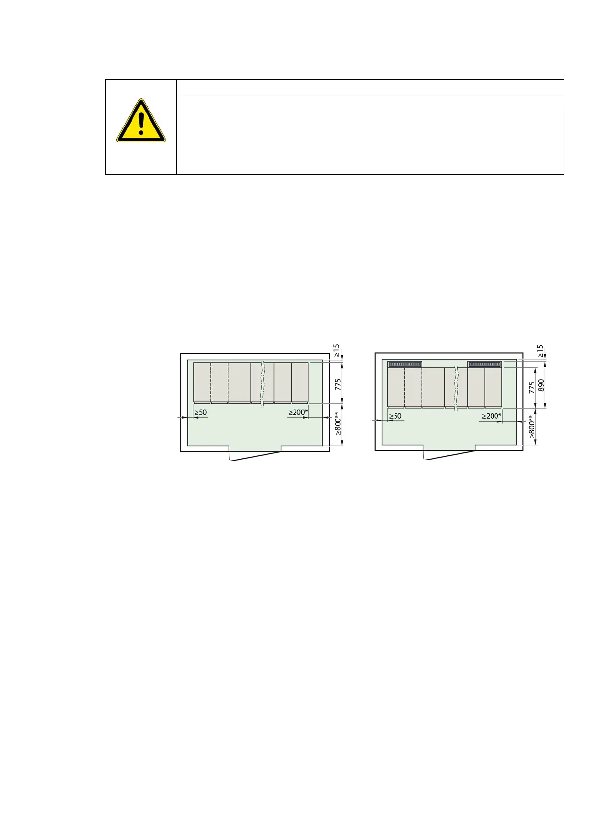
Fig. 24: Pressure relief downwards
(standard)
Fig. 25: Pressure relief with pressure relief
duct at the rear
* For lined up switchgear
** Depending on national requirements. For extension or panel replacement, a control aisle of at least
1000 mm is recommended.

 Loading...


