500-8067.9 • INSTALLATION AND OPERATING INSTRUCTIONS • 8DJH • Revision 05 55/121
Installation
12.7 Preparing the foundation
• A suitable foundation can be a false floor, a double floor or a reinforced-concrete
foundation. The reinforced-concrete floor must be equipped with foundation rails for
supporting the panels.
• As for design and construction of the foundation, the relevant standards DIN 43661
“Fundamentschienen in Innenanlagen der Elektrotechnik” (Foundation rails in electrical
indoor installations) and DIN 18202 “Maßtoleranzen im Hochbau” (Blatt 3) (Measuring
tolerances in structural engineering (Sheet 3)) apply.
• The dimensions of the floor opening and the fixing points of the switchgear frame are given
in the switchgear documentation.
• Determine level differences between the installation surfaces of the panels using a
measuring sheet, and compensate with shims.
Stipulations for evenness
and straightness
Evenness/straightness tolerance according to DIN 43661: 1 mm for 1m length, 2mm over
the width of the complete switchgear.
12.8 Unpacking the switchgear
➭ Remove the PE foil; if required, remove seaworthy or latticed crate before.
➭ If necessary, remove the front cable compartment cover from the subframe of the
switchgear.
➭ Remove the fixing bolts of the transport angles and keep them for later reuse.
➭ Remove transport angles.
If the switchgear cannot be lifted directly from the wooden pallet onto its mounting position,
please proceed as follows:
➭ Lower the transport units by means of the lateral transport angles onto roller pads
(reinforced rollers) or tubes.
➭ Lift the switchgear at the side edges with roller crowbars and slowly lower it onto the
mounting position.
➭ Remove transport angles.
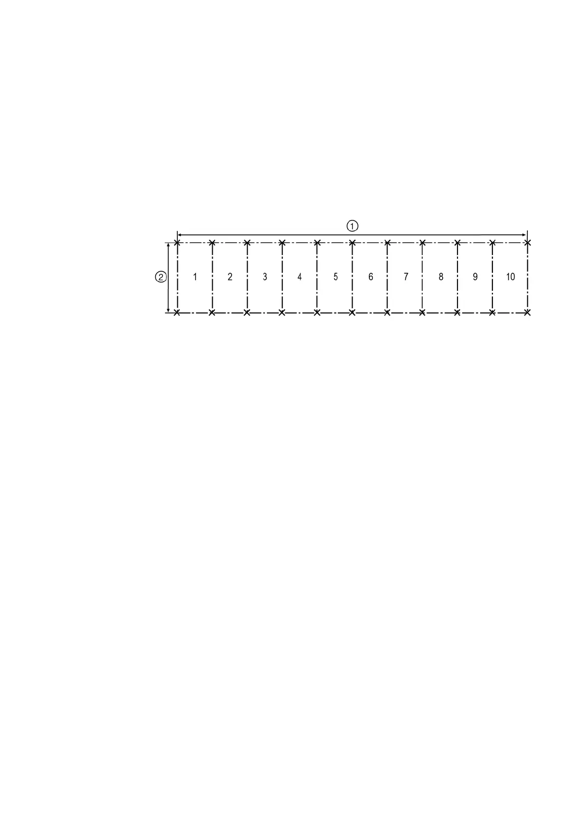
Fig. 26: Measuring sheet for the foundation
①
Width of complete switchgear
②
750 mm

 Loading...


