EasyManuals Logo

Siemens CPU 313C Hardware And Installation Guide

Siemens CPU 313C
238 pages
To Next Page IconTo Next Page
To Previous Page IconTo Previous Page
Page #108 background imageLoading...
Page #108 background image
$GGUHVVLQJ
S7-300 Automation System, Hardware and Installation: CPU 31xC and CPU 31x
8-4 A5E00105492-03
The byte address depends on the module start address.
The bit address is the number printed on the module.
Insert the first digital module into slot 4 so that it has default start address 0. The
start address of every subsequent digital module will be incremented by 4 per slot
(see diagram under 6ORWEDVHGPRGXOHDGGUHVVLQJ
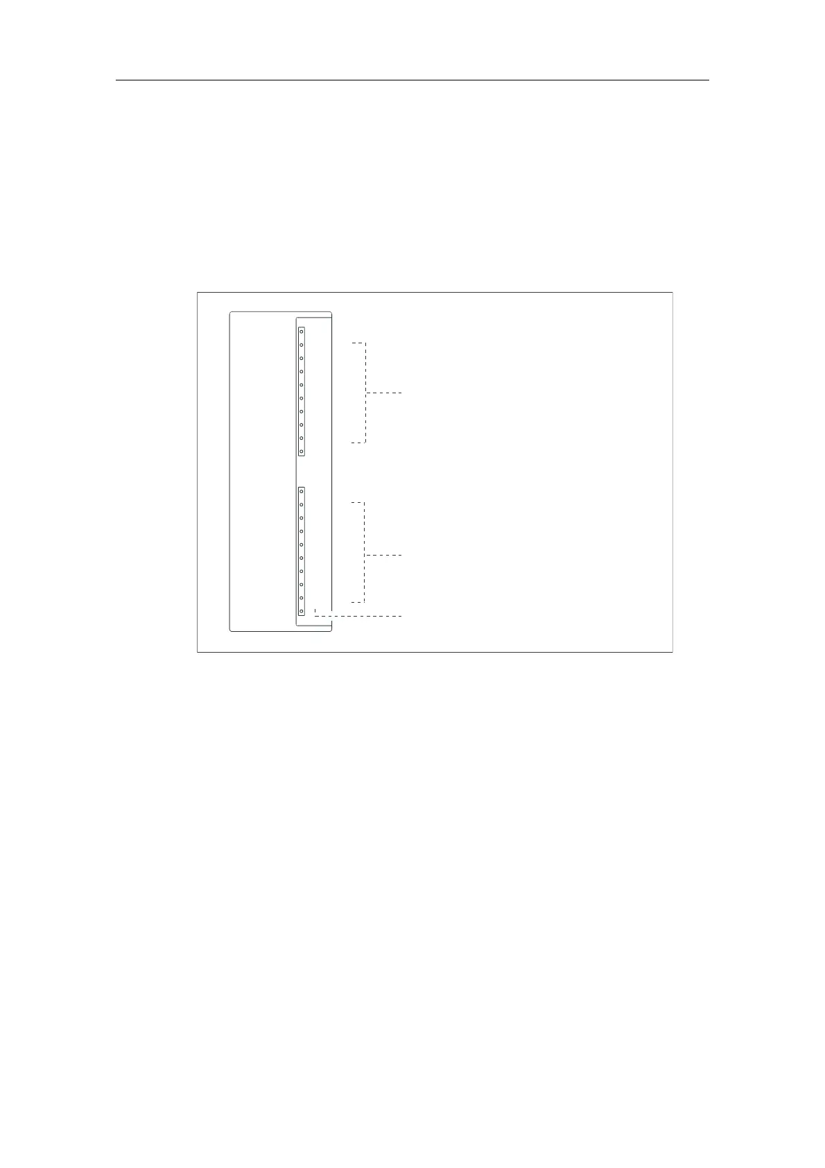
The figure below shows you how the addresses of the individual channels of a
digital module are obtained.
0
1
2
3
4
5
6
7
0
1
2
3
4
5
6
7
Byte address:
start address of modules
Byte address:
start address of modules + 1
Bit address
Figure 8-2 Addresses of the I/O of digital modules

Table of Contents

Other manuals for Siemens CPU 313C

Questions and Answers:

Question and Answer IconNeed help?

Do you have a question about the Siemens CPU 313C and is the answer not in the manual?

Siemens CPU 313C Specifications

General IconGeneral
MPI InterfaceYes
Number of digital inputs24
Number of digital outputs16
Number of analog inputs4
Number of analog outputs2
Supply voltage24 V DC
High-speed countersYes
Bit Operations Execution Time0.1 µs
Word Operations Execution Time0.2 µs
Power Consumption5 W
Dimensions (W x H x D)40 x 125 x 130 mm
Operating Temperature0 to 60 °C
Communication InterfacesMPI
Programming LanguagesLAD, FBD, STL
Product type designationCPU 313C
Weight490 g

Related product manuals