EasyManuals Logo

Siemens CPU 313C Hardware And Installation Guide

Siemens CPU 313C
238 pages
To Next Page IconTo Next Page
To Previous Page IconTo Previous Page
Page #156 background imageLoading...
Page #156 background image
0DLQWHQDQFH
S7-300 Automation System, Hardware and Installation: CPU 31xC and CPU 31x
10-10 A5E00105492-03
3RVLWLRQRIWKH)XVHV
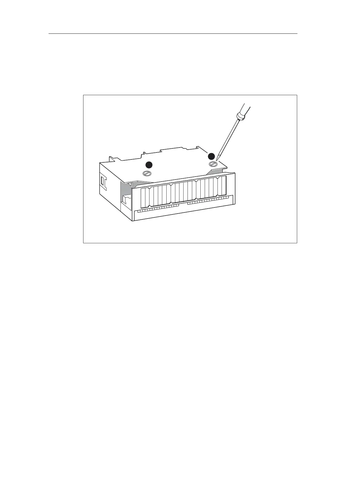
Digital output modules are equipped with 1 fuse per channel group. The fuses are
located at the left side of the digital output module. The figure below shows you the
location of the fuses on digital output modules.
1
1
Figure 10-5 Location of fuses in the digital output module 120/230 VAC
5HSODFLQJIXVHV
The fuses are located at the left side of the module. Replace the fuses as follows:
1. Switch the CPU to STOP.
2. Switch off the load voltage of the digital output module.
3. Remove the front connector from the digital output module.
4. Loosen the fixing screw of the digital output module.
5. Swing out the digital output module.
6. Remove the fuse holder from the digital output module ).
7. Replace the fuse.
8. Screw the fuse holder back into the digital output module.
9. Reinstall the digital output module.

Table of Contents

Other manuals for Siemens CPU 313C

Questions and Answers:

Question and Answer IconNeed help?

Do you have a question about the Siemens CPU 313C and is the answer not in the manual?

Siemens CPU 313C Specifications

General IconGeneral
MPI InterfaceYes
Number of digital inputs24
Number of digital outputs16
Number of analog inputs4
Number of analog outputs2
Supply voltage24 V DC
High-speed countersYes
Bit Operations Execution Time0.1 µs
Word Operations Execution Time0.2 µs
Power Consumption5 W
Dimensions (W x H x D)40 x 125 x 130 mm
Operating Temperature0 to 60 °C
Communication InterfacesMPI
Programming LanguagesLAD, FBD, STL
Product type designationCPU 313C
Weight490 g

Related product manuals