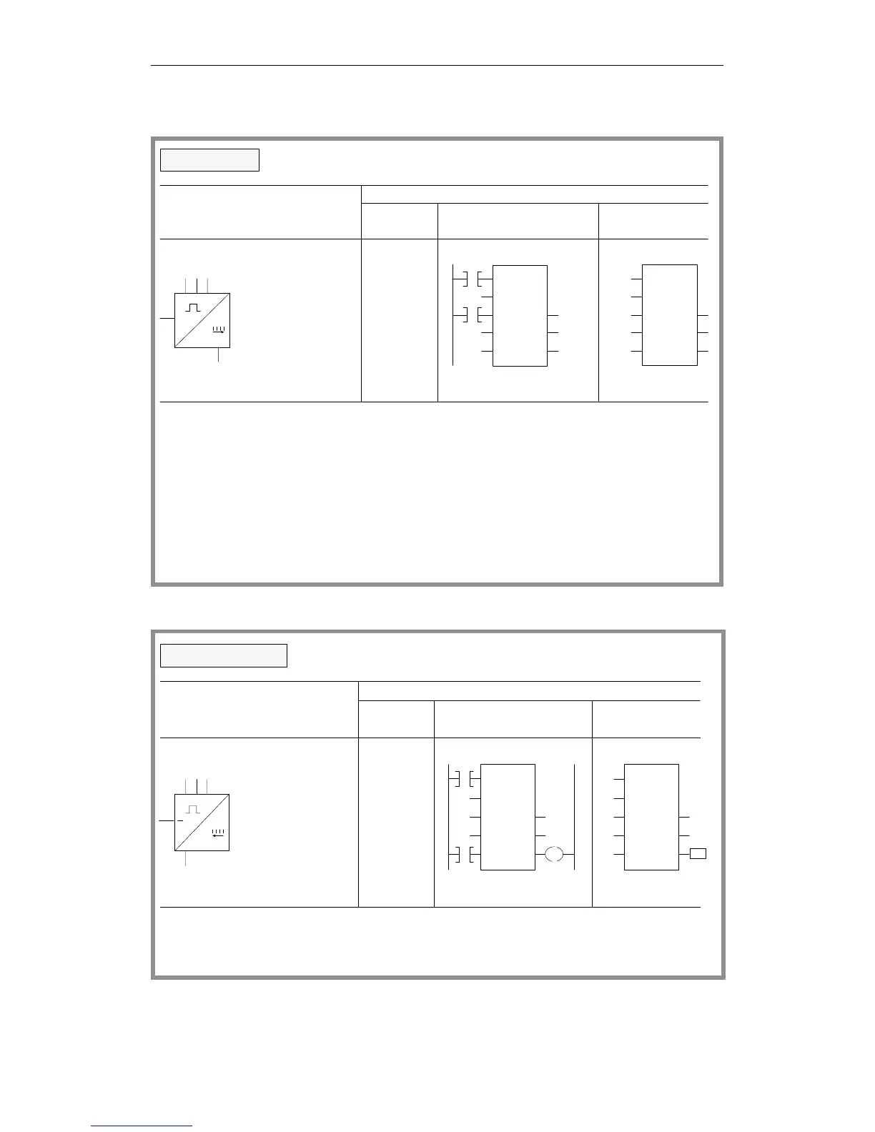
Counter operations
When the result of logic operation changes at the start input
(I 4.1) from "0" to "1", the counter is loaded with the specified
is incorporated in the counter word.
BI and DE are digital outputs of the counter cell. The
value at BI is in binary code and the value at DE is in
BCD.
I 4.1
RS
CQ
CI
+
binary
16 bits
KC 150
KC 150
CD
BI
DE
RQ
C1
CU
S
CV
I 4.1
CD
BI
DE
RQ
C1
CU
S
CV
value (150).
Logical/circuit operation
STEP 5 representation
Ladder Control system
Statement
list
Set counter
I 4.1
I 4.0
I 4.0
A
CU
A
L
S
I
C
I
KC
C
4.0
1
4.1
150
1
diagram flowchart
The flag necessary for edge evaluation of the set input
KC 150
I 4.2
RSCI
binary
16 bits
CU
BI
DE
RQ
C2
CD
S
CV
An RLO of "1" (I 4.2) resets the counter to zero.
Q 2.4
Q 2.4
CQ
I 4.2
CU
BI
DE
RQ
C2
CD
S
CV
Q 2.4
=0 /
An RLO of "0" does not affect the counter.
Logical/circuit diagram
STEP 5 representation
Ladder Control system
Statement
list
Reset counter
A
CD
A
R
A
=
I
C
I
C
C
Q
4.0
2
4.2
2
2
2.4
I 4.2
I 4.0
I 4.0
=
diagram flowchart
Programming Examples in the STL, LAD and CSF Methods of Representation
CPU 948 Programming Guide
3 - 44 C79000-G8576-C848-04