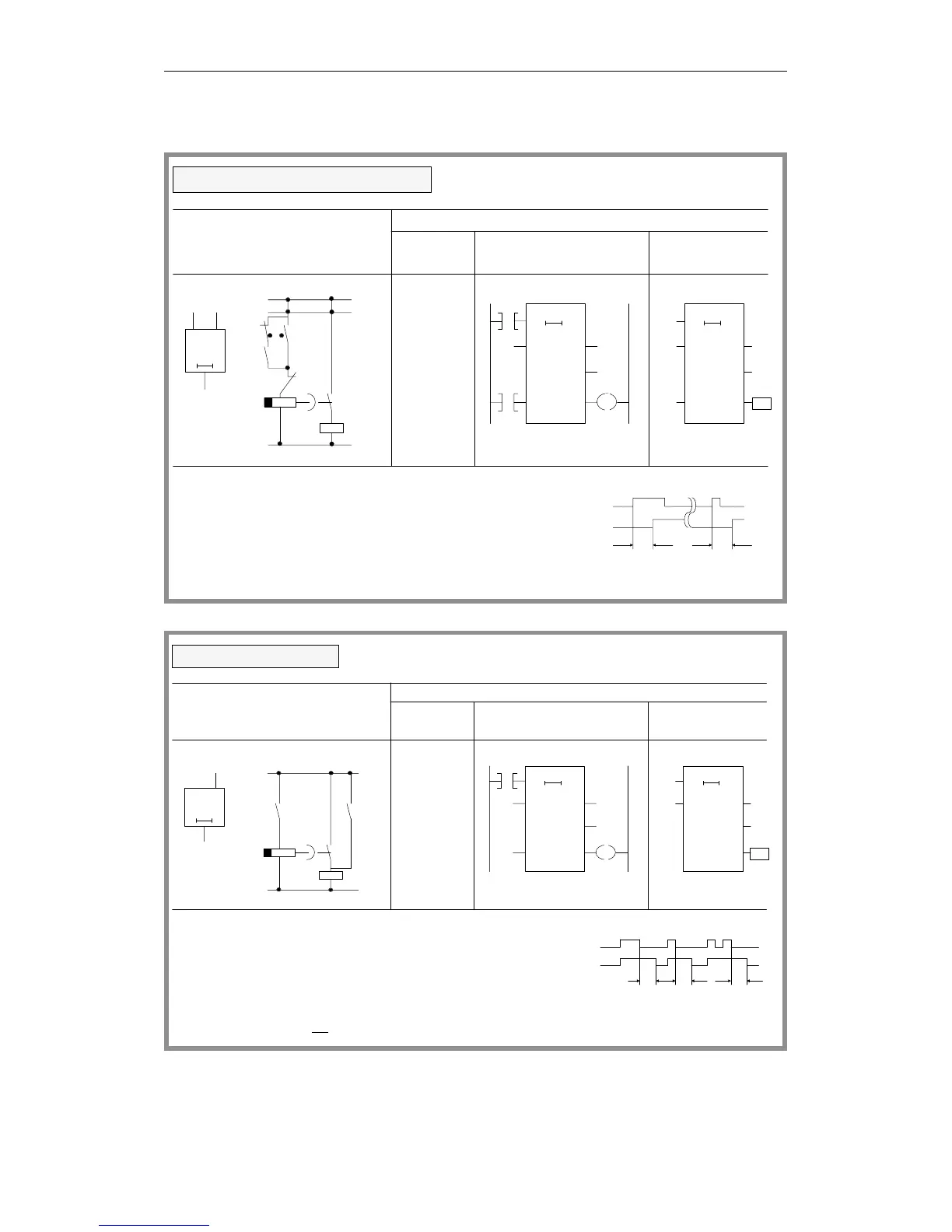
Timer operations (continued)
TS
TV
BI
DE
RQ
I 3.3
Q 4.3
I 3.2 I 3.3
Q 4.3
T4
Q 4.3
RS
20s 0
I 3.3
T4
I 3.2
I 3.2
TS
BI
DE
RQ
I 3.3
I 3.2
T4 T4
I 3.3
Q 4.3
TT
timer has elapsed. The signal state does not change
to "0" until the R T operation resets the timer.
The timer is started during the first scan if the RLO is "1".
An RLO of "0" does not affect the timer.
T4
= Q 4.3
A
I
3.3
L KT 20.2
SS
T4
A I 3.2
RT4
AT4
E
The scan AT or OT produces the signal "1" when the
Logical/circuit diagram
STEP 5 representation
Ladder Control system
Statement
list
Stored ON-delay timer
20.2 TV
Q 4.3
=
20.2
diagram flowchart
I 3.4
Q 4.4
I 3.4
Q 4.4
T5
Q 4.4
RS
01
I 3.4
T5
OT
TV
BI
DE
RQ
OT
BI
DE
RQ
I 3.4
T5 T5
T5
A
I
=Q
3.4
L KT 10.1
SF
T5
AT5
4.3
I 3.4
Q 4.4
TTT
The scan AT or OT produces signal state "1" if
the timer is running
When the RLO is "1", the timer is reset (cleared).
When the RLO at the start input changes from "1" to
"0", the timer is started. It runs for the length of time
programmed.
Logical/circuit diagram
STEP 5 representation
Ladder Control systemStatement
list
OFF-delay timer
10.1
TV
10.1
Q 4.4
=
diagram flowchart
or
the RLO at the input is "1".
Programming Examples in the STL, LAD and CSF Methods of Representation
CPU 948 Programming Guide
C79000-G8576-C848-04
3 - 43