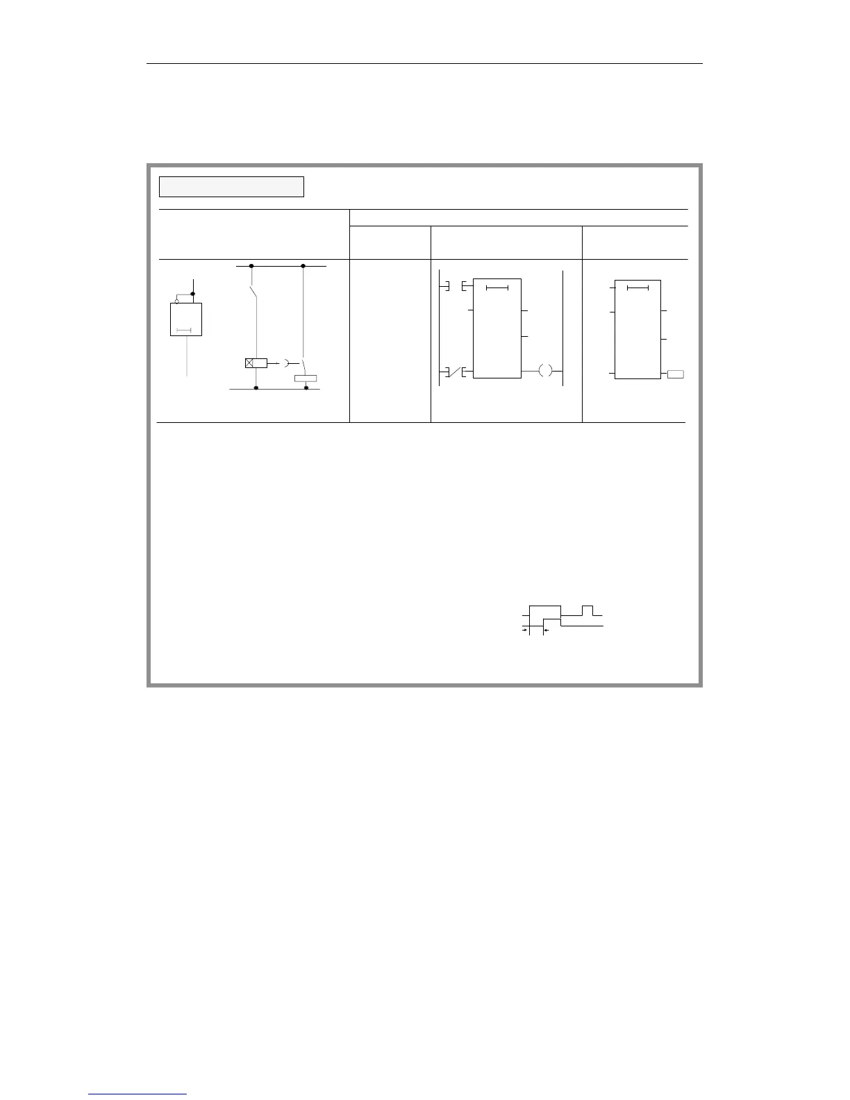
Timer operations (continued)
The timer is started during the first scan if the RLO
is "1". An RLO of "1" during subsequent scans does
Q
KT9.2
T3
TW
BI
Q4.2
DE
I 3.5
Q
KT9.2
T3
TV
Q4.2
DE
R
Q4.2
R
I 3.5
T 3
RS
I 3.5
T 3
9s
0
Q4.2
BI
TO TO
When the RLO is "0", the timer is reset (cleared).
not affect the timer.
KT 9.2:
The timer is loaded with the specified value (9). The
number to the right of the decimal point indicates
0 = 0.1sec 2 = 10 sec
I 3.5
Q4.2
T
The scan AT or OT produces the signal "1" when the
timer has elapsed and the RLO is still applied to the
input.
Logical/circuit diagram
STEP 5 representation
Ladder Control system
Statement
list
ON-delay timer
I
KT
T
I
T
T
Q
3.5
9.2
3
3.5
3
3
4.2
A
L
SD
AN
R
A
=
I 3.5
I 3.5
=
diagram flowchart
the time base:
3 = 10 sec1 = 0.1 sec
Programming Examples in the STL, LAD and CSF Methods of Representation
CPU 948 Programming Guide
3 - 42 C79000-G8576-C848-04