Timer operations (continued)
The timer is started during the first scan if the RLO is
"1".
A I 3.1
L IW 15
SE T 2
T 2A
Q 4.1=
I 3.1
Q
IW15
T2
1
TW BI
Q4.1
DE
I 3.1
Q
IW15
T2
1
TW BI
Q4.1
DE
R
Q4.1
V
R
V
Q4.1
I 3.1
T 2
R
S
1
T2
I 3.1
T 2
(IB 15) (IB 16)
An RLO of "0" does not affect the timer.
The scan AT or OT produces a signal "1" as long as
the timer is running.
IW 15:
Set the timer with the value of the operand I, Q, F or
D in BCD code (in this example, input word 15).
I 3.1
Q4.1
TT
Timer value
Time
base
5 43 07 43 0
0
1010
1
10
2
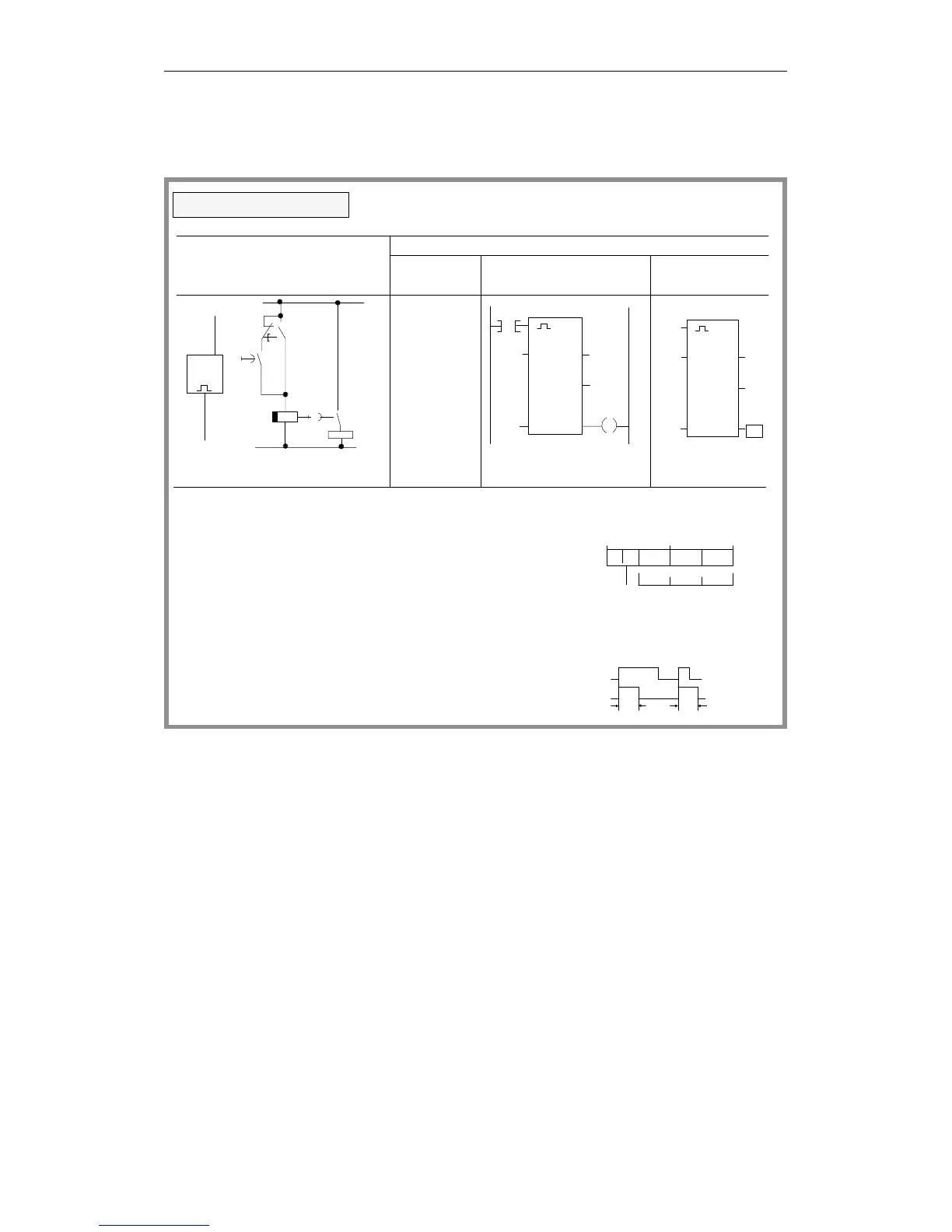
Logical/circuit diagram
STEP 5 representation
Ladder Control system
Statement
list
Extended pulse timer
=
diagram flowchart
Programming Examples in the STL, LAD and CSF Methods of Representation
CPU 948 Programming Guide
C79000-G8576-C848-04
3 - 41