Address Areas for
Peripherals and
Programming Them
Using STEP 5 operations, you can access peripherals either directly or
via the process image (PI). Note that a process image exists only for
input and output bytes of the "P" peripherals with byte addresses from
0 to 127!
Note
Using the interface modules IM 304, IM 307 and IM 308, you can
access distributed address areas using your program. This allows
access to two new address areas similar to the O area. In contrast
to the O area, however, access to these areas is only possible
using absolute addressing or using FB 196 of the "basic
functions" software package (refer to Catalog ST59).
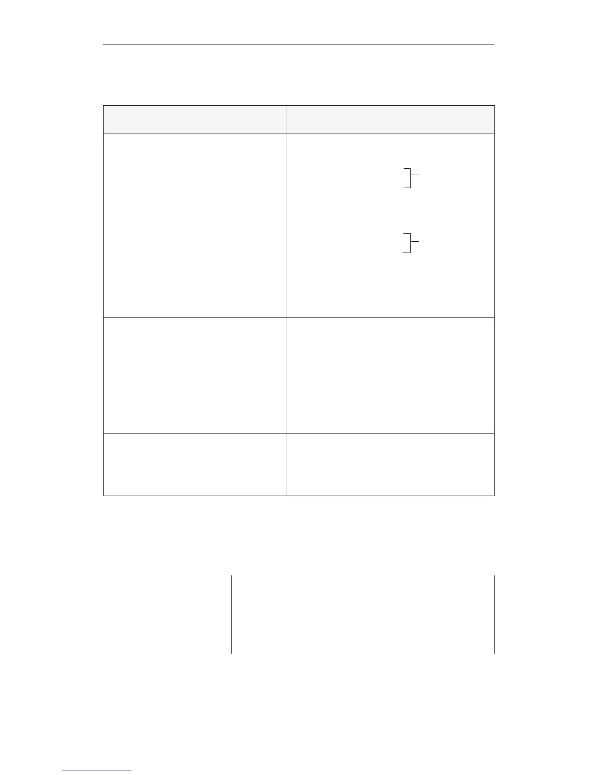
Area
(absolute address)
Referenced with Parameter
"P" peripherals with process image
L IB / T IB 0 to 127
L IW / T IW 0 to 126
L ID / T ID 0 to 124
A I/ AN I / O I / ON I 0.0 to 127.7
S I / R I / = I
L QB / T QB 0 to 127
L QW / T QW 0 to 126
L QD / T QD 0 to 124
A Q / AN Q / O Q / ON Q 0.0 to 127.7
S Q / R Q / = Q
When the operation is processed, only the process
image is changed. The new status of the process
image of the outputs is only output to the I/Os at
the end of the cycle.
"P" peripherals
L PY / T PY 0 to 127
L PW / T PW 0 to 126
L PY / T PY 128 to 255
L PW / T PW 128 to 254
The inputs and outputs are addressed directly in
bytes or words.
"O" peripherals
L OY / T OY 0 to 255
L OW / T OW 0 to 254
The inputs and outputs are addressed directly in
bytes or words.
PII
(Process image input)
PIQ
(Process image output)
Digital peripherals
Inputs/outputs
Digital or analog
peripherals
Inputs/outputs
Extended peripherals
Inputs/outputs
E FE00
E FEFF
E FE80
E FE7F
F F000
F F07F
F F080
F F0FF
F F100
F F1FF
Memory Assignment in the CPU 948
CPU 948 Programming Guide
C79000-G8576-C848-04
8 - 9