4BMounting / Installation
| 138
2015-11-04
5.19.2.1 Use of unshielded cables
The connection is established from base to base using twisted or non-twisted wire
pairs.
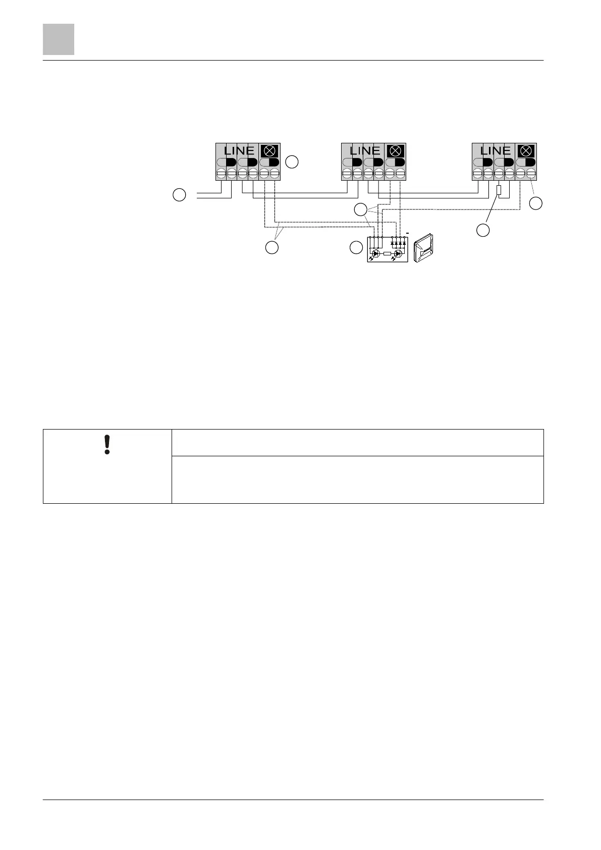
Connection diagram for collective detector line with and without external alarm indicators (without
shielded cables)
1
Control panel 3
External alarm indicator
2
Detector bases FDB201/FDB201-AA, FDB202 4
End-of-line depending on control panel
Standard circuitry
With standard circuitry, the external alarm indicator is connected to the positive and
negative poles of each detector.
Wire-saving cabling
Wire-saving cabling in external alarm indicators is prohibited for new sites
● The base adapter FDB299 must be used for the FDOOT241-A9.
With wire-saving cabling, the external alarm indicator is connected as follows:
● The external alarm indicator must be connected to the positive and negative
poles of at least one detector (A).
● The external alarm indicator must be connected to the positive pole of every
other detector (B).
● The external alarm indicator need not be connected to the negative pole of
every other detector (C).
+
-
+
-
+
-
+
-
+
-
+
-
LINE
+
-
+
-
+
-
+
-
1
2
C
4
B
3
A
+
 Loading...