4BMounting / Installation
105 |
2015-11-04
5.19.3.2 Use of shielded cables
The shielding of the MS8 detector line must be connected in the base adapter to
auxiliary terminals DBZ1190-xx.
If a shielded cable is used, there are two possible ways of connecting external
alarm indicators:
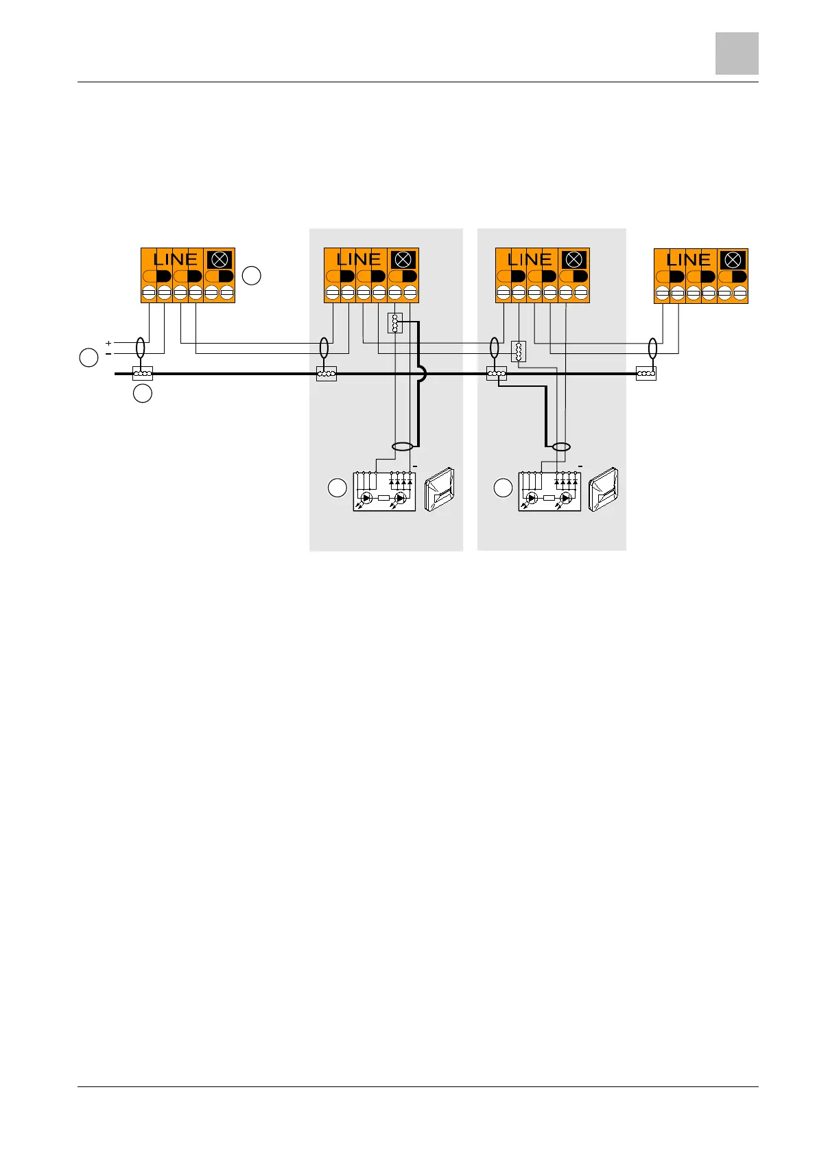
Connection diagram for MS8 detector line with and without external alarm indicators (with shielded
cables)
1 Control panel 3 Auxiliary terminals DBZ1190-xx
2 Base adapter FDB281 (with fitted detector
base FDB221)
4 External alarm indicator
Variant A:
1. Connect the positive pole of the external alarm indicator to the positive pole for
the alarm indicator on the detector.
2. Connect the negative pole of the external alarm indicator to the negative pole
for the alarm indicator on the detector.
3. Connect the shielding of the connection cable between the alarm indicator and
detector on the detector side to the positive pole for the external alarm indicator
via a DBZ1190-xx auxiliary terminal.
+
-
+
-
+
-
+
-
+
-
+
-
LINE
+
-
+
-
+
-
1
2
3
B
4
+
+
A
+
-
+
-
+
-
4
 Loading...


