4BMounting / Installation
| 138
2015-11-04
5.19.4.3 Connecting external alarm indicators
The points below apply to connecting external alarm indicators:
● If the external alarm indicator is connected to only one individual detector, there
is no limitation.
● If only original AnalogPLUS detectors and FDOOT241-A3 with base adapter
FDB241 are used, there is no limitation.
● If several FDOOT241-A3 are merged with detector base FDB22x on an
external alarm indicator in Sinteso, external alarm indicator FDAI9x must be
used.
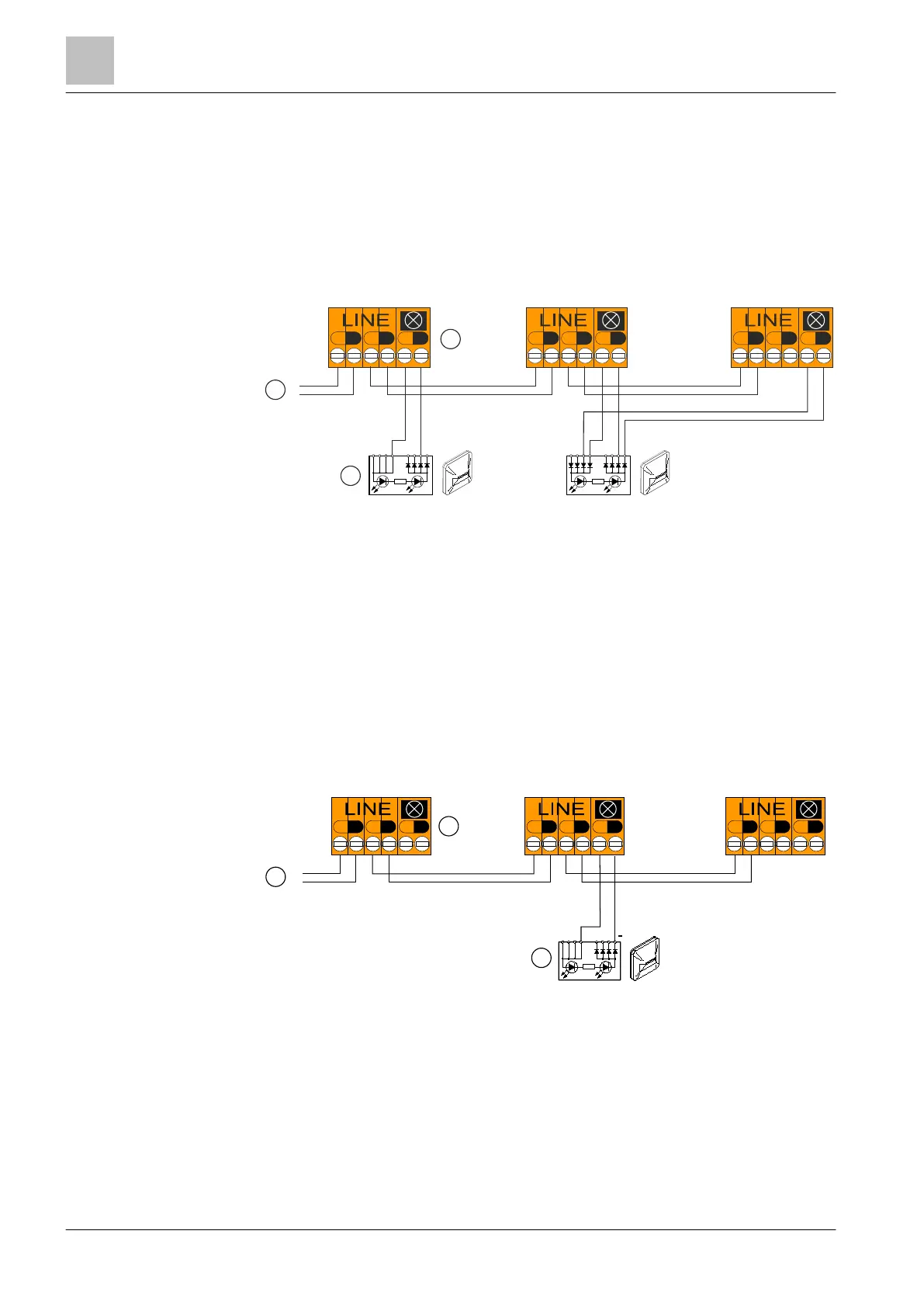
Connecting external alarm indicators
1 Control panel
2 Sinteso detector base FDB22x
3 External alarm indicator
5.19.5 Connection diagram for SIGMALOOP detector line
5.19.5.1 Use of unshielded cables
The connection is established from base to base using twisted or non-twisted wire
pairs.
Connection diagram for SIGMALOOP detector line with and without external alarm indicators (without
shielded cables)
1
Control panel
2
Base adapter FDB241
3
External alarm indicator
+
-
+
-
+
-
+
-
+
-
+
-
LINE
+
-
+
-
+
-
FDAI9x
+
-
+
-
+
-
1
2
3
+
-
+
-
+
-
+
-
+
-
+
-
LINE
+
-
+
-
+
-
+
-
1
2
3
+
 Loading...