4BMounting / Installation
| 138
2015-11-04
5.19 Detector lines
General cabling information
● Preferably, twisted and non-shielded cables should be used. This also applies
to connecting the external alarm indicators.
● Shielded cables are only required in special cases, such as strong high-
frequency fields.
See also
Detector lines [➙ 120]
5.19.1 Connection diagram for FDnet detector line
The following applies to FDnet detector lines:
● Loops, stubs and T-branches are possible.
● You may only connect external alarm indicators to one detector.
● Permissible cables for detectors with more than one external alarm indicator in
the collective, AnalogPLUS, and SIGMALOOP connection diagrams may be
migrated to the FDnet without any changes.
● Note document 001508 for installation (calculation of the capacity layer).
See also
Applicable documents [➙ 9]
5.19.1.1 Use of unshielded cables
The connection is established from base to base using twisted or non-twisted wire
pairs.
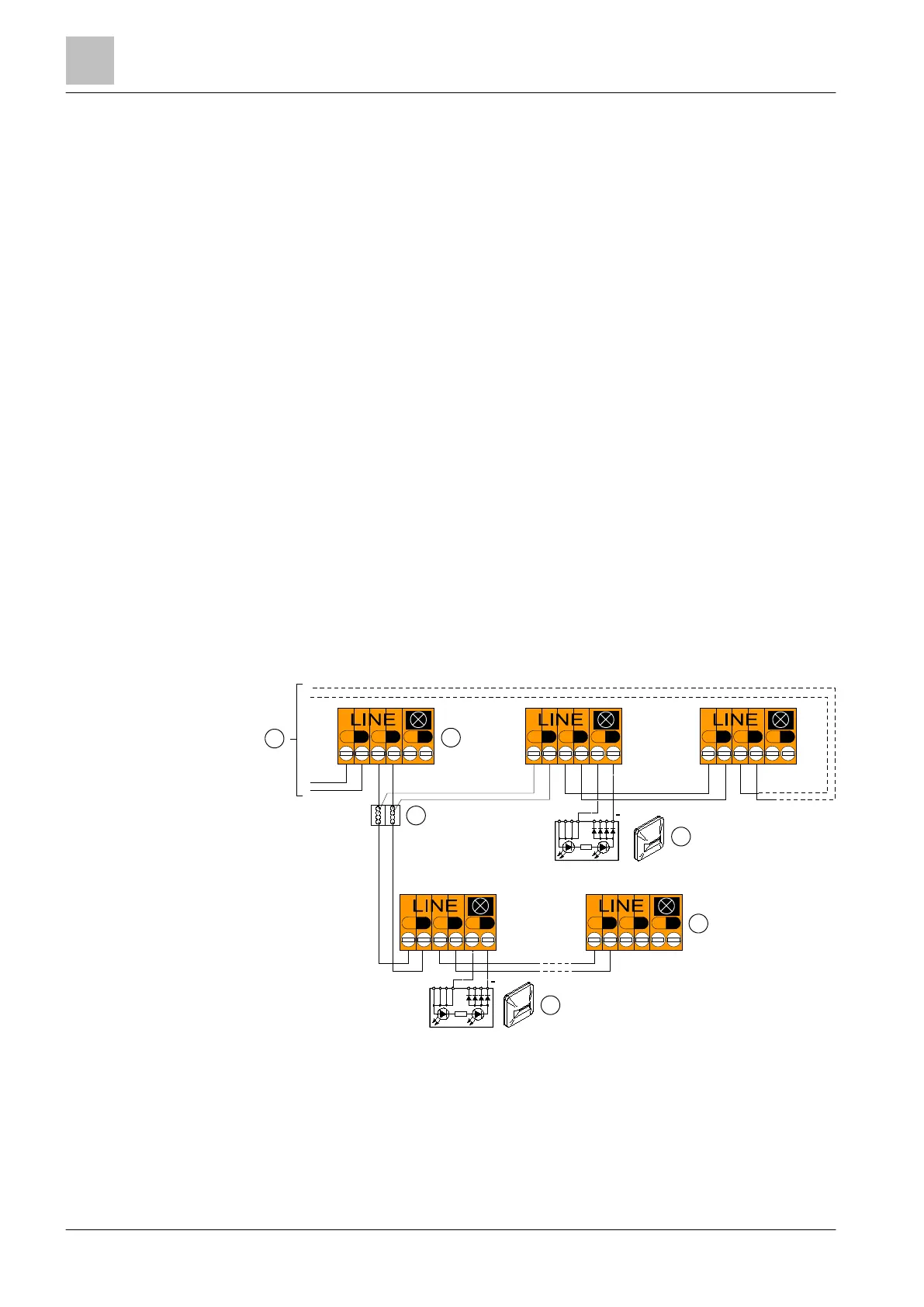
Connection diagram for addressed detector line with and without external alarm indicators (without
shielded cables)
1
Control panel 3 Auxiliary terminals DBZ1190-xx
2
Detector bases FDB221/FDB221-AA, FDB222 4 External alarm indicator
+
-
+
-
+
-
+
-
+
-
+
-
LINE
+
-
+
-
+
-
+
-
+
-
+
-
+
-
-
+
+
-
+
-
+
-
1
2
3
4
2
+
4
+
 Loading...