4BMounting / Installation
| 138
2015-11-04
Variant B:
1. Connect the positive pole of the external alarm indicator to the positive pole for
the alarm indicator on the detector.
2. Leave the negative pole for the alarm indicator on the detector unoccupied.
3. Connect the negative pole of the external alarm indicator to the negative
terminal on the input side of the MS8 detector line on the detector via a
DBZ1190-xx auxiliary terminal.
4. Connect the shielding of the MS8 detector line to the shielding of the
connection cable for the external alarm indicator via a DBZ1190-xx auxiliary
terminal.
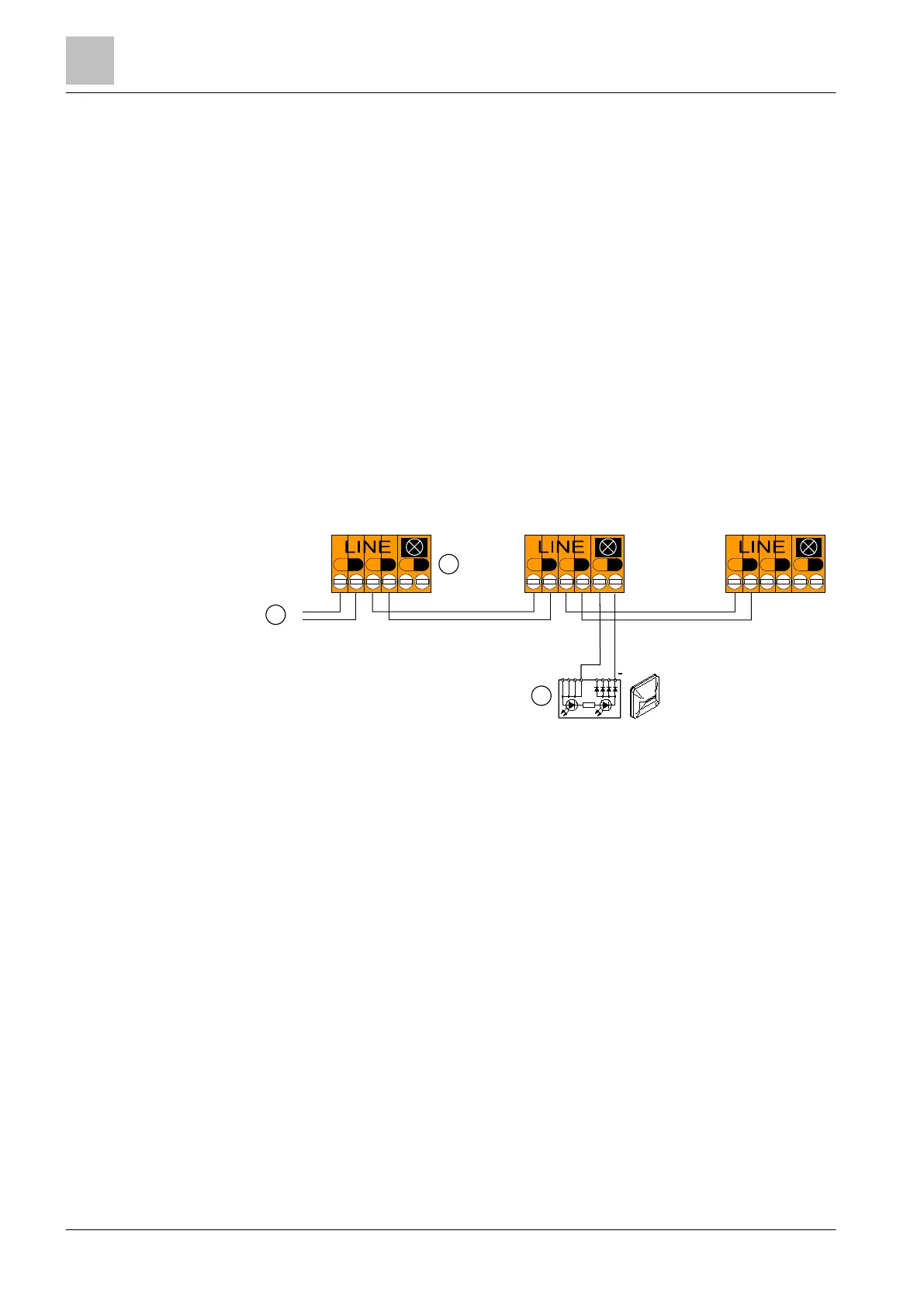
5.19.4 Connection diagram for AnalogPLUS detector line
5.19.4.1 Use of unshielded cables
The connection is established from base to base using twisted or non-twisted wire
pairs.
Connection diagram for AnalogPLUS detector line with and without external alarm indicators (without
shielded cables)
1
Control panel
2
Base adapter FDB241
3
External alarm indicator
+
-
+
-
+
-
+
-
+
-
+
-
LINE
+
-
+
-
+
-
+
-
1
2
3
+
 Loading...