42/106
Building Technologies Basic Documentation LME7... CC1P7105en
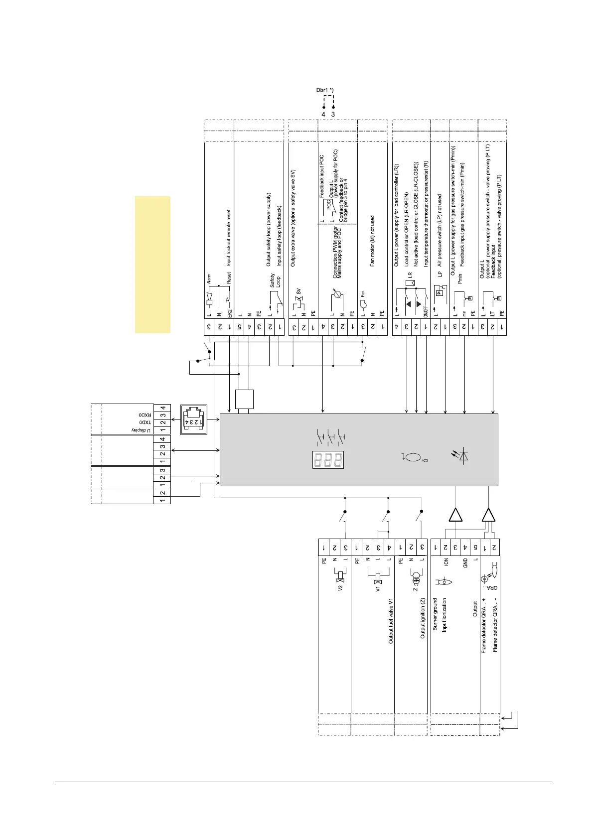
9 Connection diagram AGG9 connector 17.04.2018
9 Connection diagram AGG9 connector
9.1 LME71
X56
AGG9. 822 83 1 841
GND
Coding
Connector marking
NT
N L
K7
K5
F SV2
FSV1
K4
K1
K2/1
µC
O utp ut fu el va lve V2
K2/2
+
-
A
/reset
Not us ed
Note!
*) If POC not used,
wire link Dbr1 must be connected!
Β
BCI
AGG9. 310 405 304 504 209
03K34
03K66
05K37
02K43
05K30 03K57
03K105
02K02
03K54
03K30
04K77
AGG9. 302 501 309 401 301 403 203 306 313
03K15
Figure 9: Connection diagram LME71 ↑ AGG9

 Loading...
