EasyManuals Logo

Siemens LME7 Series User Manual

Siemens LME7 Series
106 pages
To Next Page IconTo Next Page
To Previous Page IconTo Previous Page
Page #43 background imageLoading...
Page #43 background image
43/106
Building Technologies Basic Documentation LME7... CC1P7105en
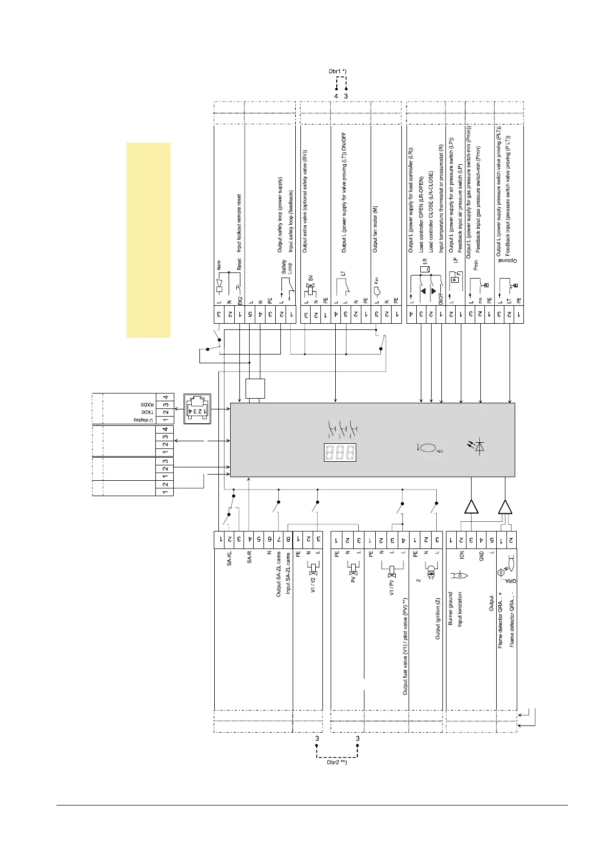
9 Connection diagram AGG9 connector 17.04.2018
9.2 LME73
X56
AGG9. 822 831 841
7
1
0
5
d
1
1
0
e
n
/
0
3
1
6
GND
Coding
Pl ug marking
NT
N L
L
M
E
7
3
.
0
0
0
.
.
.
L
E
D
K12
K11
K9
K2/2
K7
K5
F SV2
FSV1
K4
K1
K2/1
SA-NL
SA-CLOS E
N
o
t
u
s
e
d
L
R
-
I
N
(
a
n
a
l
o
g
)
µC
+
-
A
B
C
I
Outp ut p ilo t valve (PV )
O
u
t
p
u
t
a
l
a
r
m
I
n
p
u
t
v
a
l
v
e
p
r
o
v
i
n
g
(
L
T
)
O
N
/
O
F
F
O utp ut fu el valv e (V1 / V2) **)
G
N
D
L
R
i
n
p
u
t
5
V
p
o
w
e
r
s
u
p
p
l
y
S
i
g
n
a
l
G
N
D
Not active
P
L
T
/reset
V
a
l
v
e
p
r
o
v
i
n
g
O
N
/
O
F
F
Note!
*) If valve proving is not use,
wire link Dbr1 can be connected!
**) Depending on fuel train.
Β
BCI
03K34
03K66
05K37
02K43
05K30
03K57
03K105
02K02
03K54
03K30
04K77
AGG9. 302 501 309 401 301 403 203 306 313
03K15
04K22
04K01
03K10
AGG9. 601 201 311 310 405 304 504 209
08K24
Figure 10: Connection diagram LME73 AGG9

Table of Contents

Other manuals for Siemens LME7 Series

Questions and Answers:

Question and Answer IconNeed help?

Do you have a question about the Siemens LME7 Series and is the answer not in the manual?

Siemens LME7 Series Specifications

General IconGeneral
BrandSiemens
ModelLME7 Series
CategoryController
LanguageEnglish

Related product manuals