System overview
3.3 System configuration
CMK2000
Operating Instructions, 11/2015, A5E34877550B/001
17
System configuration
System configuration
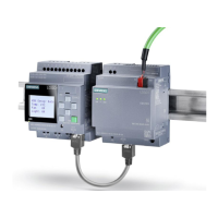
The following picture shows a basic system configuration with a CMK2000 as the
communication module between LOGO! and KNX.
Image 3-2 CMK2000 configuration example
Tasks and meanings of the system components
The CMK2000 communication module allows the transfer and system-compatible scaling of
data between KNX and LOGO!.
Depending on the parameter assignment in the ETS, the data flow is either from LOGO! to
KNX or vice versa from KNX to LOGO!.
The CMK2000 is connected over Ethernet to the LOGO! 8. The power supply to the
CMK2000 is made using an external power unit with 24 V DC.
The bus cable between CMK2000 and the KNX system is implemented as a two-wire
connection (twisted pair). The bus cable provides the KNX nodes with data and also the
operating voltage of 29 V DC from the KNX power supply.
Configuration / parameter assignment / commissioning of the CMK2000 is carried out using
a personal computer with the ETS (Engineering Tool Software) via a KNX interface such as
USB or IP interface.

 Loading...


