The original SYSCON consists of a single controller board. The newest version of SYSCON,
called SYSCON2, is a base SIB (SYSCON Interface Board) with an attached CAC3
(Communication and Control board). The SYSCON combines all data results and performs
additional high level data processing and calculations. The SYSCON connects to a color
touchscreen display, strip chart recorder, other analyzers, printers, the Advance
Communication System (ACS), or other connected networks.
The SYSCON is the analyzer control system in addition to containing the application database.
The application database also contains analytical hardware database definitions that are used
to perform the following functions:
● Obtain desired sampling measurements
● I/O and SNE schedule of timing events
● Sequence of sampling streams
● Calculations of reported values
● Formatting of results and location and
outputting results
● How to report or correct error conditions
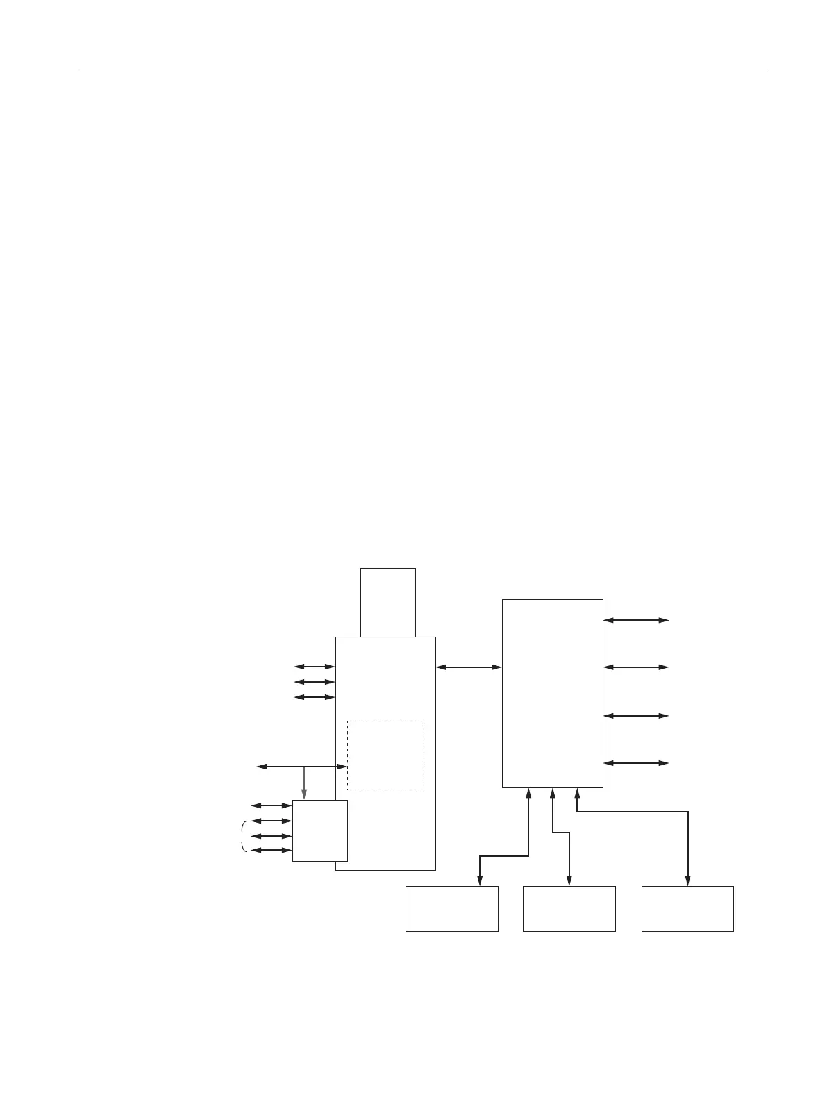
3.4 Data Communication
Internal Communication
An I
2
C Internal Bus provides communication between the SYSCON, SVCM, EPC, PECM and
to the I/O bus. External communication is through an Ethernet link. The interface for each type
of module is described in the Component Descriptions and Maintenance Procedures section.
Software SNE
DPM 3
Software SNE
DPM 2
I
2
C I
2
C I
2
C
Sampling
System
I
2
C
CAC3
CAN
RS485
RS232
Analyzers
GCP
Ethernet
Ethernet
Switch
(optional)
I/O
Boards
I
2
C
I
2
C
EPCs
SVCMs
Ethernet
I
2
C
I
2
C
GCP
Color
Touch
Display
SYSCON
(SIB3)
PECM
Controller
Board
Software SNE
DPM 1
Figure 3-3 Data Communication Paths
System Functions
3.4 Data Communication
Maxum edition II Analyzer General Maintenance
Manual, August 2018, A5E42019842001 17

 Loading...


