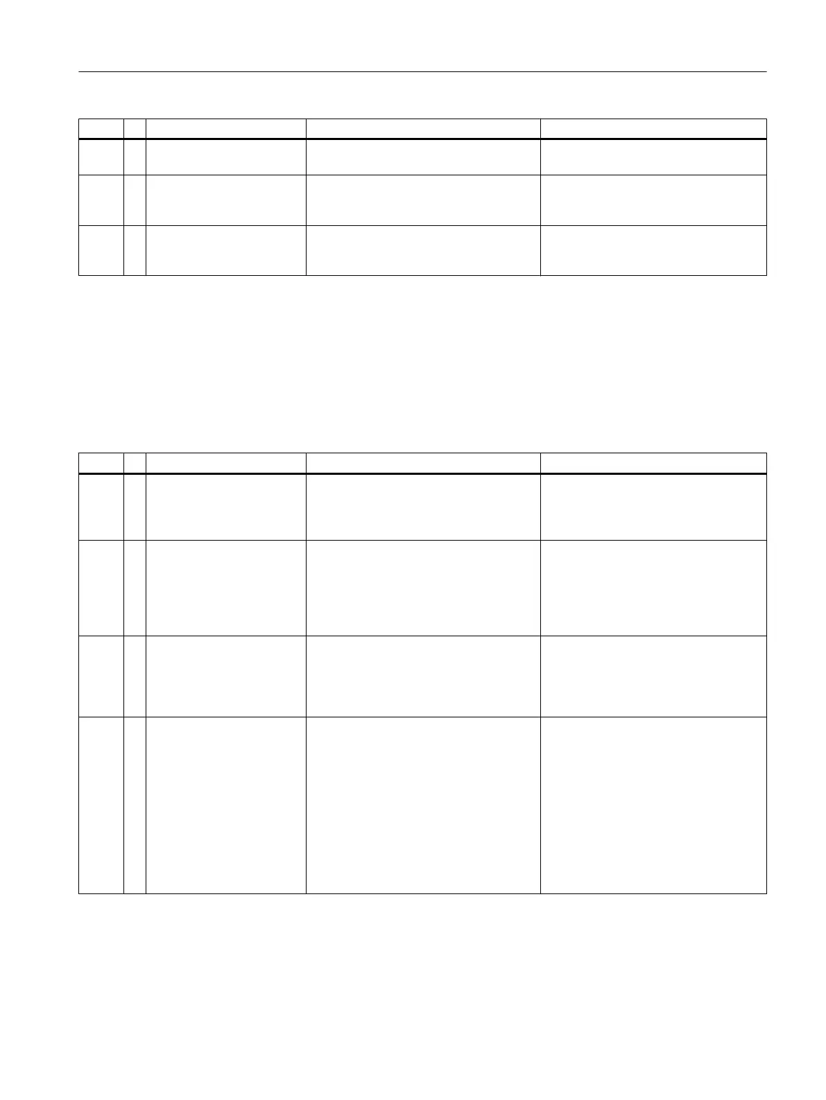
# Text Description Action
997 + %3 General alarm used for information.
Used most often by MaxBasic programs.
No action necessary.
998 ? %3 General warning alarm used for informa‐
tion. Used most often by MaxBasic pro‐
grams.
Immediately report runtime errors to
Customer Support (please make care‐
ful note of the alarm message).
999 ! %3 General fault alarm used for information.
Used most often by MaxBasic programs.
Immediately report runtime errors to
Customer Support (please make care‐
ful note of the alarm message).
4.6.8 Alarms 1002 - 1128
GCP Alarm Descriptions 1002 - 1128 SNE Common Module Errors
The following tables list the alarm number (#), type (+ information, ? warning, ! error) alarm
text, description, and actions.
# Text Description Action
1002 ! ID Key Not Connected on
%4
All PICs: The module location ID connec‐
tor is disconnected or set to 0. This is an
abnormal condition; the module may not
be operational.
Verify that the location ID connector is
in good condition and connected prop‐
erly.
1003 ! ID Key Change on %4 All PICs: The module location ID value
was changed while the module was op‐
erating. This is a transient error that cau‐
ses the module to automatically reset.
The module can then be addressed and
operated at the new location ID.
Verify that the location ID connector is
in good condition and connected prop‐
erly.
Check for intermittent connection.
1004 ! EEPROM Bad Checksum
on %4
All PICs: A checksum error was detected
in the module EEPROM. The firmware
will still use all the information that it can
read from the EEPROM. However, the
module may not operate normally.
Cycle power.
If the error repeats, replace the module.
1005 ? Temp Diag Error on %4 All PICs: The on-board temperature sen‐
sor (LM-75) diagnostic failed. This alarm
indicates that the ability of the board to
detect a module overheat (alarm #1044)
may be compromised. This alarm is may
happen occasionally following a board
reset.
This alarm is in no way related to and
should not be confused with the Over‐
temp Shutdown related to heater temper‐
ature controls.
No action is required unless the error
happens every time the board is reset.
For these repetitive errors replace the
module.
General Maintenance and Troubleshooting
4.6 Alarm Codes, Descriptions, and Suggested Actions
Maxum edition II Analyzer General Maintenance
Manual, August 2018, A5E42019842001 47

 Loading...


