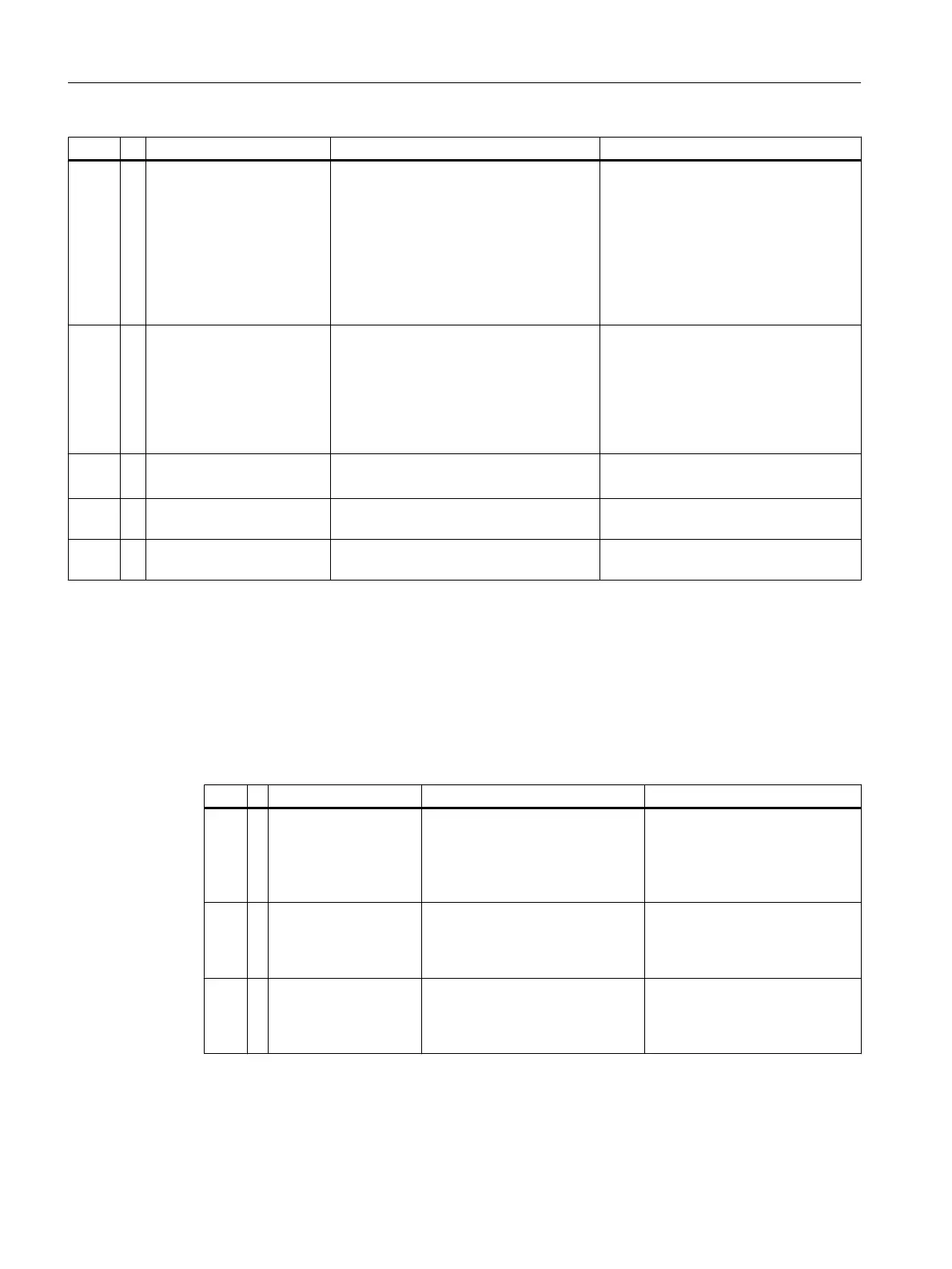
# Text Description Action
1124 ! Firmware Watchdog on %4 All PICs: The PIC watch dog timer has
expired causing a module reset. This flag
is always associated with a FIRM‐
WARE_FAULT flag. It can be an indica‐
tion that the I2C clock or data line was
held low for more than the timeout dura‐
tion (nominally 30 ms). It can also indi‐
cate that the PIC oscillator is not working
normally.
Cycle power.
If the error repeats, replace the module.
1125 ! Firmware System Monitor
on %4
All PICs: The background system moni‐
toring task has discovered a problem
causing the PIC to be reset. It can be that
the interrupt or timer were disabled when
they should have been enabled, or some
similar error. This flag is always asso‐
ciated with a FIRMWARE_FAULT flag.
Cycle power.
If the error repeats, replace the module.
1126 ! Firmware Application on
%4
All PICs: A general PIC firmware error
was encountered causing a board reset.
Cycle power.
If the error repeats, replace the module.
1127 ! Firmware Stack Overflow
on %4
An abnormal condition was detected in
the firmware of a specified module.
Reset the device. If the condition per‐
sists, replace the affected module.
1128 ! Firmware Unknown Reset
on %4
An abnormal condition was detected in
the firmware of a specified module.
Reset the device. If the condition per‐
sists, replace the affected module.
4.6.9 Alarms 1317 - 1319
GCP Alarm Descriptions 1317 - 1319
The following tables list the alarm number (#), type (+ information, ? warning, ! error) alarm
text, description, and actions.
# ! Text Description Action
131
7
! Valve Switch Error on
%4
SVCM PIC: The SVCM firmware
has detected an invalid condition
in the circuit driving the solenoid
valves. One or more valves is
likely to be malfunctioning.
Replace the module.
131
8
! J10 Disconnected on
%4
SVCM PIC: The SVCM J10 con‐
nector is not properly connected
and the corresponding bank of
solenoids may not work.
Check the J10 connection.
131
9
! J11 Disconnected on
%4
SVCM PIC: The SVCM J11 con‐
nector is not properly connected
and the corresponding bank of
solenoids may not work.
Check the J11 connection.
General Maintenance and Troubleshooting
4.6 Alarm Codes, Descriptions, and Suggested Actions
Maxum edition II Analyzer General Maintenance
52 Manual, August 2018, A5E42019842001

 Loading...


