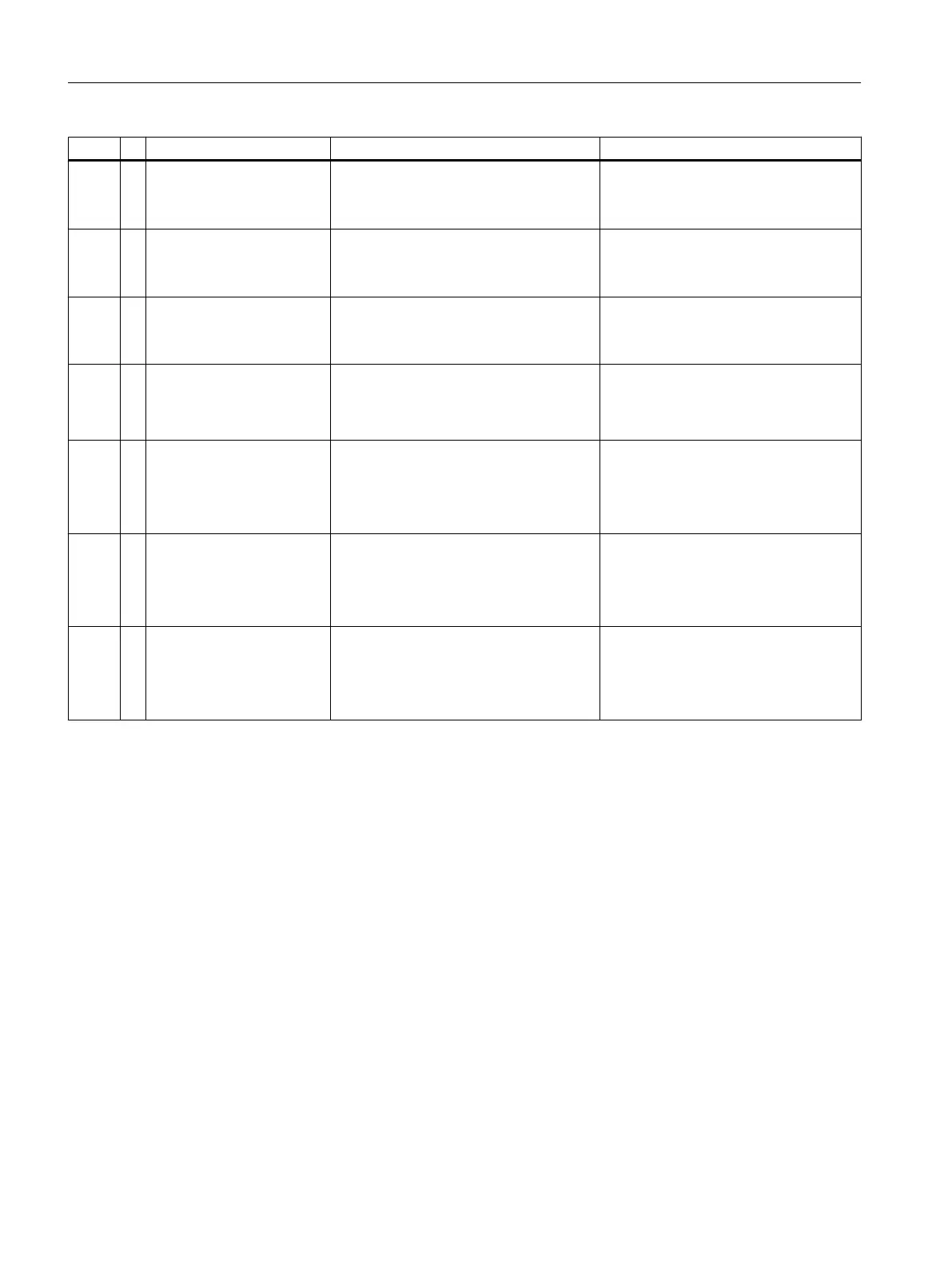
# Text Description Action
2571 ? I2C FPGA Recovery Failed
on %4
SNECON I2C driver: SNECON firmware
internal error (SNECON revision 3.0
hardware only).
Reset the analyzer.
Reload the SNECON OS software.
Replace the SNECON.
2572 ? I2C FPGA Read in pro‐
gress not set after header
on %4
SNECON I2C driver: SNECON firmware
internal error (SNECON revision 3.0
hardware only).
Reset the analyzer.
Reload the SNECON OS software.
Replace the SNECON.
2573 ? I2C Not enough memory in
ISR on %4
SNECON I2C driver: SNECON firmware
internal error (SNECON revision 3.0
hardware only).
Reset the analyzer.
Reload the SNECON OS software.
Replace the SNECON.
2574 ! I2C PIC Reset Detected on
%4
SNECON I2C driver: A problem was de‐
tected by a SNECON PIC and it went
through a reset. Can also be caused by
an I2C communication error.
If occurring frequently, replace the SNE‐
CON.
2575 ? I2C General AO error on
%4
SNECON I2C driver: A channel specific
error was detected while an AO com‐
mand was processed (Example AO out
of range) . A more specific alarm will be
reported by the module on the next poll.
Provides the channel information for an
alarm reported on the same module.
2576 ? I2C General DO error on
%4
SNECON I2C driver: A channel specific
error was detected while an DO com‐
mand was processed (Example DO out
of range) . A more specific alarm will be
reported by the module on the next poll.
Provides the channel information for an
alarm reported on the same module.
2577 ? I2C bus configuration
changed
The configuration between internal I2C
(5V I2C) and external, SSSI (10V I2C)
was changed. The configuration change
is ignored until the next reset.
If the configuration was changed inten‐
tionally, simply reset the device. Other‐
wise, verify that the cable in J3 and J13
on SNECON V4 or J1 and J3 on the SIB
are properly inserted.
General Maintenance and Troubleshooting
4.6 Alarm Codes, Descriptions, and Suggested Actions
Maxum edition II Analyzer General Maintenance
66 Manual, August 2018, A5E42019842001

 Loading...


