Pin Signal name Type Pin Signal name Type
39 Output 5.0 O 40 Output 5.1 O
41 Output 5.2 O 42 Output 5.3 O
43 Output 5.4 O 44 Output 5.5 O
45 Output 5.6 O 46 Output 5.7 O
47 DOCOM3 VI 48 DOCOM3 VI
49 DOCOM3 VI 50 DOCOM3 VI
VI: Voltage input / VO: Voltage output
I: Signal input / O: Signal output / GND: Reference potential (ground)
Digital inputs
• Characteristics:
– X222: Inputs 3.0 to 3.7 are connected as rapid inputs; this means the input lter has a
max. delay time of 600 μs.
– The inputs have no signaling (status LEDs).
– The inputs are not isolated.
– It is not possible to connect 2-wire BEROs.
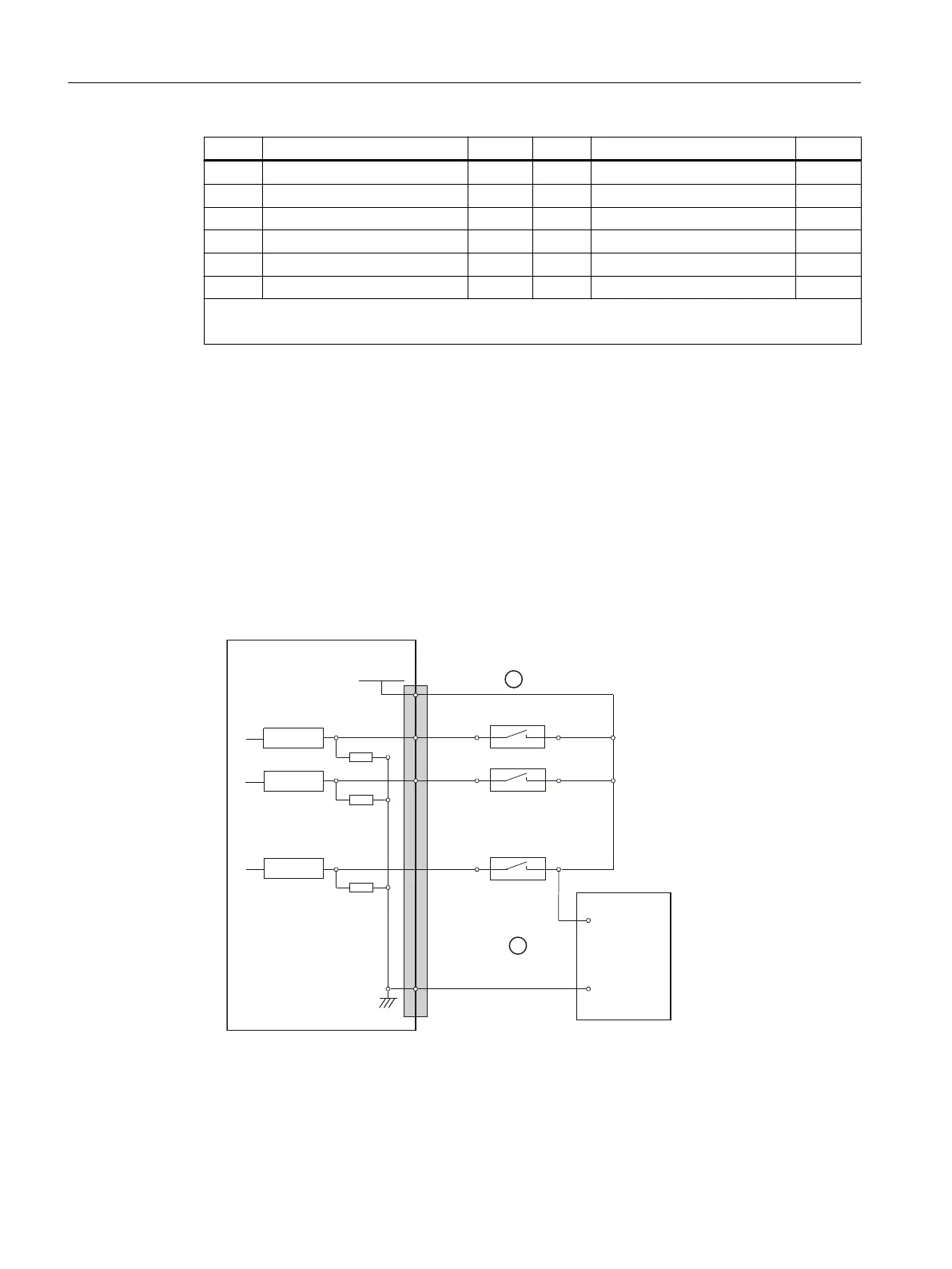
• Terminal assignment for the digital inputs:
The following gure shows an example of the terminal assignment for the digital inputs on
connector X111. Connectors X222 and X333 are assigned analogously.
3LQQXPEHU
5HFHLYHU
([WSRZHUVXSSO\
3287H[W
VWDELOL]HG
5HFHLYHU
5HFHLYHU
33'31
;;;
3287
9'&
0
9
9
① when using the internal power supply P24OUT
② when using an external power supply P24OUT
ext
Figure 9-11 Terminal assignment for the digital inputs
Connectable components
9.2 PP 72/48D PN
NCU 7x0.3B PN
112 Equipment Manual, 10/2020, 6FC5397-1EP40-6BA1
 Loading...


