Digital outputs
• Characteristics
– No galvanic isolation.
– Protection against: Short-circuit, overtemperature, and loss of ground.
– Automatic disconnection in case of undervoltage.
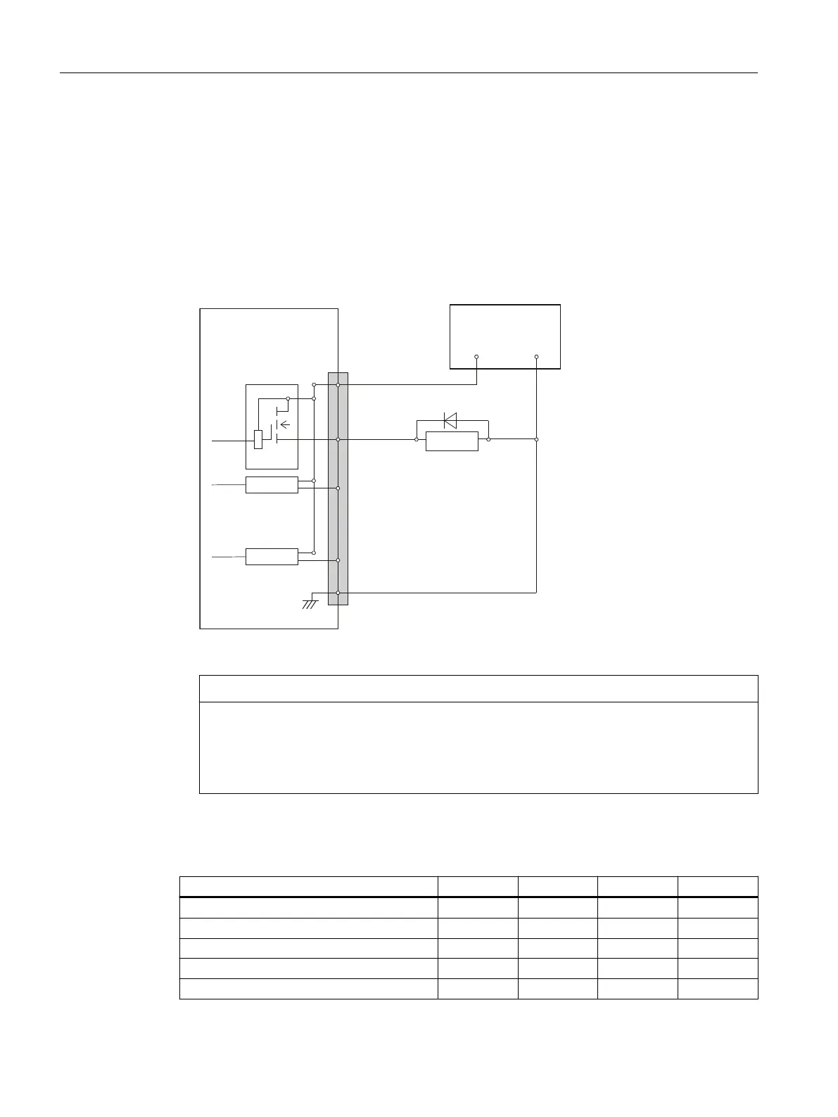
• Terminal assignment for the digital outputs:
The following gure shows an example of the terminal assignment for the digital outputs on
connector X111. Connectors X222 and X333 are assigned analogously.
([WSRZHUVXSSO\
9'&VWDELOL]HG
;;;
3LQQXPEHU
'ULYHU
'ULYHU
'ULYHU
5HOD\
33'31
9
9
'2&20[
:
:
:
:
1 (M)
0
Figure 9-12 Terminal assignment for the digital outputs
NOTICE
Damage to the module
If the outputs are overloaded, the heat can melt the contacts.
Therefore, for a demand factor of 100%, a max. current of I
out
= 0.25 A at X111, X222, X333:
Pin 2, must not be exceeded.
• Technical data:
Table 9-25 Electrical specication of the digital outputs
Digital outputs min. Standard max. Nominal
High-level voltage (U
H
) V
CC
- 3 V
1)
V
CC
24 V
Output current I
OUT
- - 250 mA
2)
-
Voltage with low level (U
L
) - - - Output open
Leakage current at low level - 50 μA 400 μA -
Signal delay time T
PHL
- 0.5 ms - -
Connectable components
9.2 PP 72/48D PN
NCU 7x0.3B PN
114 Equipment Manual, 10/2020, 6FC5397-1EP40-6BA1
 Loading...


