Pin Signal
name
Signal
type
Meaning Default set‐
ting
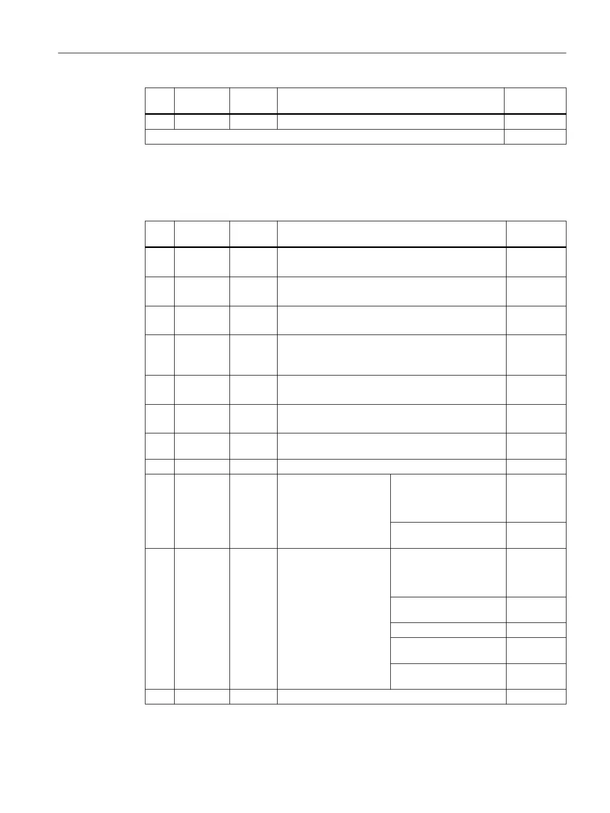
14 M GND Ground for DI8 - DI11
Signal type: B = Bidirectional; I = Input; GND = Reference potential (ground)
In the "Default setting" column, the signals for which the associated SINAMICS parameters are set when
conguring a SINAMICS device are marked with "x".
Table 7-25 X132 digital inputs/outputs
Pin Signal
name
Signal
type
Meaning Default set‐
ting
1 DI4 I Digital input 4
Freely available
---
2 DI5 I Digital input 5
Freely available
---
3 DI6 I Digital input 6
Freely available
---
4 DI7 I Digital input 7
Infeed line contactor feedback (if one infeed is operated
with a DRIVE-CLiQ connection at the NCU)
---
5 DI20 I Digital input 20
Freely available
---
6 DI21 I Digital input 21
Freely available
---
7 G2 GND Ground for DI4 – DI7 (functionally-separated relative to
M)
8 M GND Ground for DI12 - DI15
9 DI/DO12 B Digital input/output 12
(rapid input)
Output: Infeed operation
(if one infeed is operated
with a DRIVE-CLiQ connec‐
tion at the NCU)
x
Input 2. Operating condi‐
tion OFF2 drives
---
10 DI/DO13 B Digital input/output 13
(rapid input)
Output: Status, infeed
ready to start (if one infeed
is operated at the NCU with
a DRIVE-CLiQ connection)
x
Input 2. Operating condi‐
tion OFF2 drives
---
Input, external zero mark 2 ---
Input probe 2 - central
measurement
---
Input probe 2 - distributed
measurement
---
11 M GND Ground for DI12 - DI15
Connecting
7.10 Digital inputs/outputs
NCU 7x0.3B PN
Equipment Manual, 10/2020, 6FC5397-1EP40-6BA1 75
 Loading...


