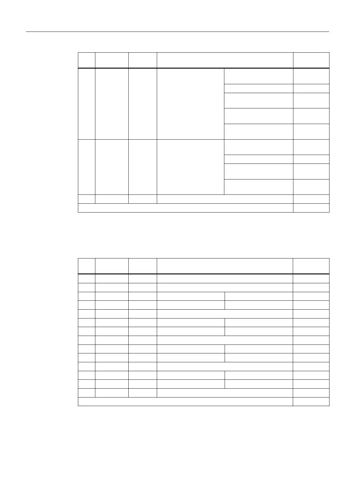
Pin Signal
name
Signal
type
Meaning Default set‐
ting
12 DI/DO14 B Digital input/output 14
(rapid input)
Input 2. Operating condi‐
tion OFF2 drives
---
Input, external zero mark 3 ---
Input probe 2 - central
measurement
---
Input probe 2 - distributed
measurement
---
Infeed, control line contac‐
tor
---
13 DI/DO15 B Digital input/output 15
(rapid input)
Input 2. Operating condi‐
tion OFF2 drives
---
Input, external zero mark 4 ---
Input probe 2 - central
measurement
---
Input probe 2 - distributed
measurement
---
14 M GND Ground for DI12 - DI15
Signal type: B = Bidirectional; I = Input; GND = Reference potential (ground)
In the "Default setting" column, the signals for which the associated SINAMICS parameters are set when
conguring a SINAMICS device are marked with "x".
Table 7-26 X142 digital inputs/outputs
Pin Signal
name
Signal
type
Meaning Default set‐
ting
1 - - Reserved, do not use ---
2 - - Reserved, do not use ---
3 IN/OUT0 B Digital NC input 1 $A_IN[1] xed
4 IN/OUT1 B Digital NC input 2 $A_IN[2] xed
5 M GND Ground for I0 - I7 ---
6 IN/OUT2 B Digital NC input 3 $A_IN[3] xed
7 IN/OUT3 B Digital NC input 4 $A_IN[4] xed
8 M GND Ground for I0 - I7 ---
9 IN/OUT4 B Digital NC output 1 $A_OUT[1] xed
10 IN/OUT5 B Digital NC output 2 $A_OUT[2] xed
11 M GND Ground for I0 - I7 ---
12 IN/OUT6 B Digital NC output 3 $A_OUT[3] xed
13 IN/OUT7 B Digital NC output 4 $A_OUT[4] xed
14 M GND Ground for I0 - I7 ---
Signal type: B = Bidirectional; GND = reference potential (ground)
Connecting
7.10 Digital inputs/outputs
NCU 7x0.3B PN
76 Equipment Manual, 10/2020, 6FC5397-1EP40-6BA1
 Loading...


