Installation
5.2 Installing a switch
SCALANCE X-300
Operating Instructions, 10/2010, A5E01113043-10
107
Desktop operation (only 24V DC variants with adhesive feet)
5. Fit the connectors for the 24 V power supply.
6. Fit the remaining connectors, for example the signaling
contact.
Removal
Removing from the rack
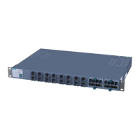
1. Turn off the power supply for the SCALANCE XR-300M.
2. Disconnect all cables for data traffic and the connectors for the power supply and the grounding cable.
3. Undo the screws on the mounting bracket and remove the rack device (R) from the 19" cabinet.
If necessary, release the locking mechanisms of components inserted in the rack device (R) (for example handles
on the media module or clips on the SFP) to be able to remove the media modules (MM900) or the transceiver
(SFP).
5.2.5 19" rack mounting - X-300EEC product group
The X-300EEC can be installed in a rack singly or as pairs.
● Mounting singly:
To do this, an X-300EEC device is secured to a plate and screwed into the 19" rack.
● Mounting as pairs:
Here, two X-300EEC devices are fastened together with plates before installation in the
rack:
– 1 plate as middle section (6 screws)
– 2 plates on the outside (3 screws each)
You will find dimension drawings of the plates in section X-300EEC dimension
dra
wings (Page 260).
 Loading...
