PROFIBUS data transfer
6.9 Cyclic data traffic
3WL/3VL circuit breakers with communication capability - PROFIBUS
140 System Manual, 03/2011, A5E01051353-02
The table below contains the definitions of the property byte:
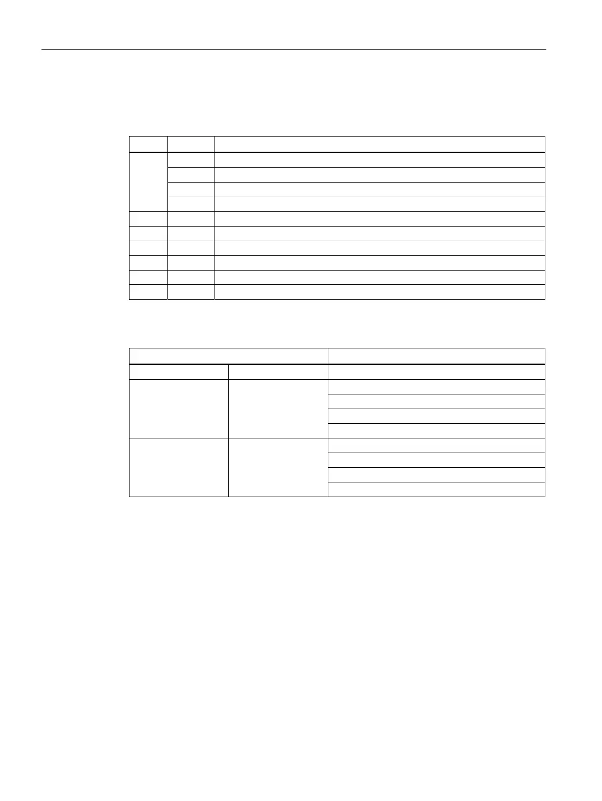
Table 6- 4 Defining of the property byte
Bit Value Description
0 Read/write
1 Read only, but can be reset (e.g. maintenance)
2 Read only, can only be written at the factory
0/1
3 Read only
2 Not used
3 Not used
4 Value in the valid range
5 Option switched on
6 Option available
7 Not used
Table 6- 5 Examples of evaluating the property byte
Value Meaning resolution
Hexadecimal Decimal
Bit 0/1 = 3 ⇒ "Read only"
Bit 4 = true ⇒ "Range valid"
Bit 5 = true ⇒ "Option switched on"
0x73 115
Bit 6 = true ⇒ "Available"
Bit 0/1 = 3 ⇒ "Read/write"
Bit 4 = true ⇒ "Range valid"
Bit 5 = false ⇒ "Option switched off"
0x50 80
Bit 6 = true ⇒ "Available"
Binary status information in the cyclic channel
The binary status information is identical in all three basic types and provides the most
important status information about the circuit breaker. It cannot be changed. The binary
status information in the cyclic channel is transferred at the start of the data frame at every
data exchange.
The binary status information consists of 2 bytes. Further explanations of data formats are
given in Chapter Data library (Page 175).
The inform
ation coding is identical in SENTRON WL and SENTRON VL provided the data is
available.
The table below contains a description of the binary status information in the cyclic frame:
 Loading...


