3WL air circuit breakers
3.5 External CubicleBUS modules
3WL/3VL circuit breakers with communication capability - PROFIBUS
System Manual, 03/2011, A5E01051353-02
77
Interfaces
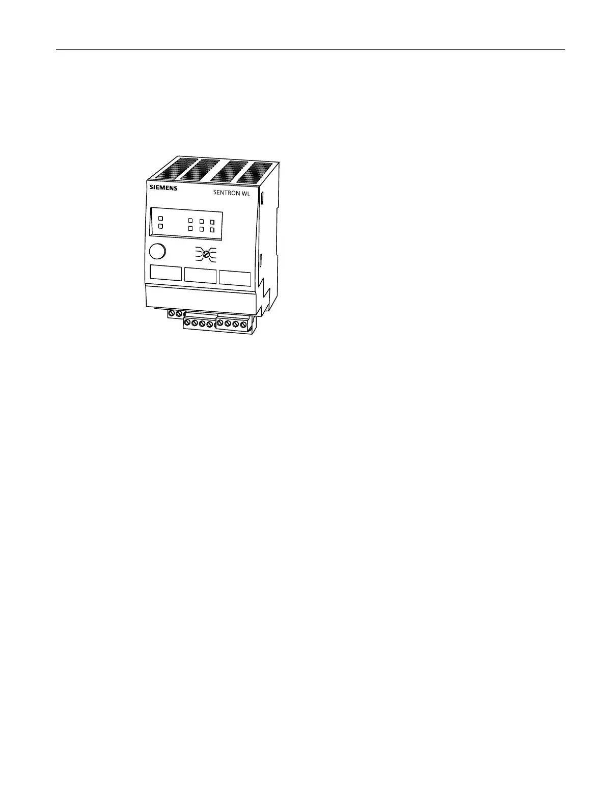
The measured values can be picked up in the form of 0 - 10 V via the X4 connector on the
CubicleBUS module, and the 4 - 20 mA interface is available on the X5 connector. Both
output forms are always active simultaneously.
Figure 3-20 Analog output module
3.5.5.1 Selecting the measured values
The measured values output via the four analog channels are selected using a rotary coding
switch. The output forms I, V, P, f and cos ϕ are available. The selection box of the rotary
coding switch is divided vertically. If the switch is set to a value in the left half, the module is
automatically addressed as Module 1, so any second module must then be set to a value in
the right half. Only in this way is simultaneous operation with two analog output modules
possible.
Maximum assignment
Up to 2 analog output modules can be operated on one CubicleBUS.
Indicators
All rotary coil instruments with an inner flow resistance of more than 20 kΩ (as voltage
output) and between 50 Ω and 250 Ω (as current output) can be used as indicator. The LEDs
for the cannels show a yellow light when the current value exceeds 20% of the full-scale
deflection value (in the case of V, I, P), or cos ϕ is greater than 0.8, or the frequency is
greater than 45 Hz.
 Loading...


