Data transfer to the PLC
7.3 Functional sequences/description of functions
3WL/3VL circuit breakers with communication capability - PROFIBUS
166 System Manual, 03/2011, A5E01051353-02
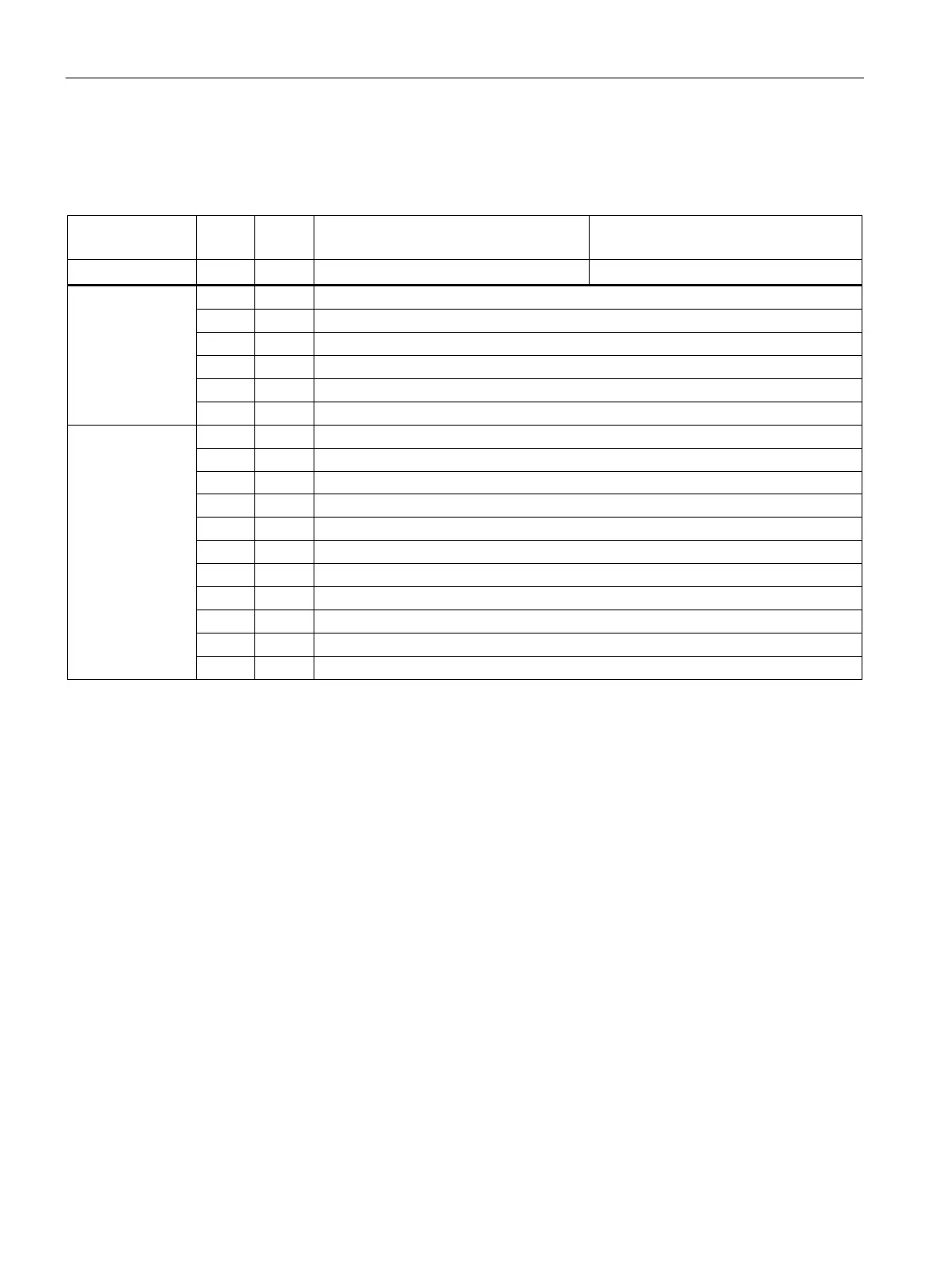
The table below explains the structure of the diagnostics of the circuit breaker.
Table 7- 2 Structure of the PROFIBUS diagnostics
Part of the
diagnostics
Byte Bit SENTRON WL SENTRON VL
COM15 COM20
0 Station status 1
1 Station status 2
2 Station status 3
3 PROFIBUS master address
4 Identification number High Byte (0x80)
DP standard
5 Identification number Low Byte (0xC0)
6 0x42 fixed
7 0 Device-specific diagnostics available
8 0x05 fixed
9 0x82 fixed
10 0x00 fixed
11 0x00 fixed
12 0x00 fixed
13 0x0F fixed
14 0x81 fixed
15 0x01 fixed
Additional header
16 0x00 fixed
 Loading...


