2
7
2
6
2
5
2
4
2
3
2
2
2
1
2
0
Format 16-bit unsigned integer
Range 0 % to 30 % of the primary voltage
Default 0
When 0 is selected, then the V
max
alarm is disabled.
V
Max
Warning
(Address 22) This register defines the maximum threshold voltage you can set for providing a warning. It is
expressed in percentage (%) of the primary voltage.
Refer to V
Max
Alarm , Page 115
V
Min
Alarm
(Address 23) This register defines the minimum threshold voltage you can set for providing an alarm. It is
expressed in percentage (%) of the primary voltage.
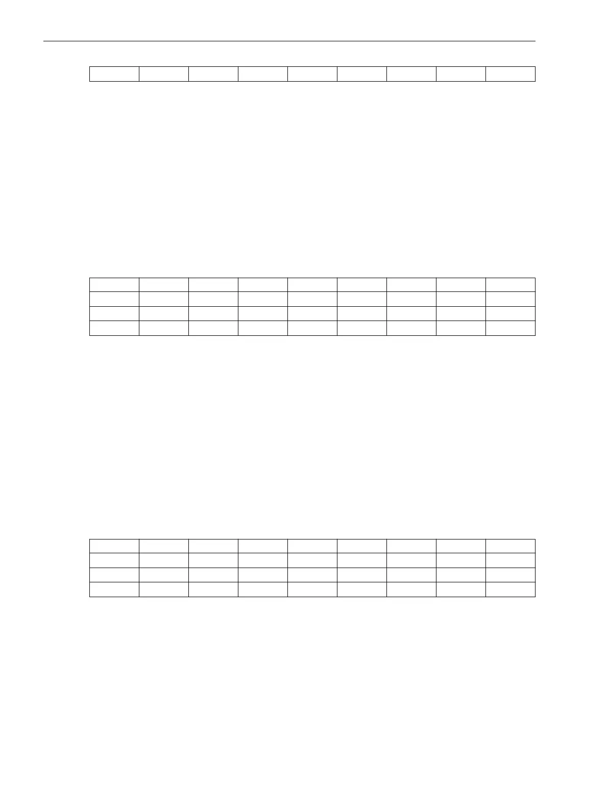
Bit 15 14 13 12 11 10 9 8
2
15
2
14
2
13
2
12
2
11
2
10
2
9
2
8
Bit 7 6 5 4 3 2 1 0
2
7
2
6
2
5
2
4
2
3
2
2
2
1
2
0
Format 16-bit unsigned integer
Range 0 % to 30 % of the primary voltage
Default 0
When 0 is selected, then the V
min
alarm is disabled.
The format used is 16-bit unsigned integer.
V
Min
Warning
(Address 24) This register defines the minimum threshold voltage you can set for providing a warning. It is
expressed in percentage (%) of the primary voltage.
Refer to V
Min
Alarm, Page 116. The format used is 16-bit signed integer.
Neutral-Point Displacement Voltage V
NG
> (Group 1)
(Address 25) This register defines the neutral-point displacement voltage. It is expressed in percentage (%).
Bit
15 14 13 12 11 10 9 8
2
15
2
14
2
13
2
12
2
11
2
10
2
9
2
8
Bit 7 6 5 4 3 2 1 0
2
7
2
6
2
5
2
4
2
3
2
2
2
1
2
0
Format 16-bit unsigned integer
Unit V
Range 0 % to 30 % of the primary voltage
When 0 is selected, then the function is disabled.
Default 30
Neutral-Point Displacement Time tV
NG
> (Group 1)
(Address 26) This register defines the neutral-point displacement time. It is expressed in milliseconds.
Modbus Registers
B.4 Register-Type Data – Holding Registers
116 SICAM, Feeder Condition Monitor, Manual
E50417-H8940-C580-A4, Edition 03.2019
 Loading...


