Mounting and connecting the device
3.3 Connecting the device
Comfort Panels
44 Operating Instructions, 08/2018, A5E36770603-AC
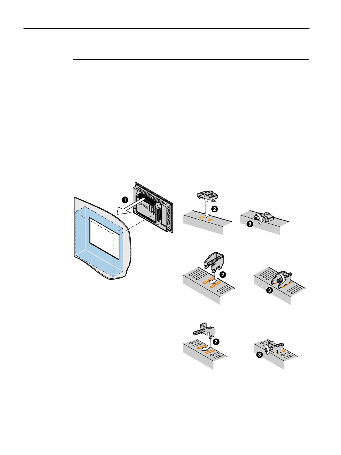
3. Tighten the set screw or the cylinder head screw to secure the mounting clip.
Note
Adhere to the permitted torque when tightening the set screw or the cylinder head screw:
4" model: 0.2 Nm
7" to 22" models: 0.5 Nm
4. Repeat steps 2 and 3 for all mounting clips.
5. Check the fit of the mounting seal.
The HMI device is mounted and the relevant degree of protection is ensured at the front.
Accessories (Page 22)
Connecting the device
3.3.1
Notes on connection
Requirement
● The HMI device must be mounted according to the specifications of these operating
instructions.
Note
Use copper cables on connectors with terminal connections
Use copper (Cu) cables for all supply lines that are connected to the device with terminals,
e.g. 24
V DC power supply cables on the 24 V DC power supply connector.
Use only shielded standard cables as data connecting cables, order information is available
in the Industry Mall (https://mall.industry.siemens.com
).