Blocks S5-115F Manual
The individual proportional-action, integral-action, and derivative-action components can be
deactivated via their particular parameters (R, TI, and TD) by presetting the pertinent data words
with zero. This enables you to implement all desired controller structures easily, e.g. PI, PD, or PID
controllers.
You can apply the control deviation XW or, using the XZ input, any disturbance variable or the
inverted actual value X to the differentiator. Specify a negative K value for an inverted control
direction.
When the correction information (dY or Y) is at a limit, the integral-action component is
automatically deactivated in order not to impair the dynamic response of the controller.
The switch settings in the block diagram are implemented when programming the PID controller.
This is done by setting the appropriate bits in the “STEU” control word ( Table 6-2).
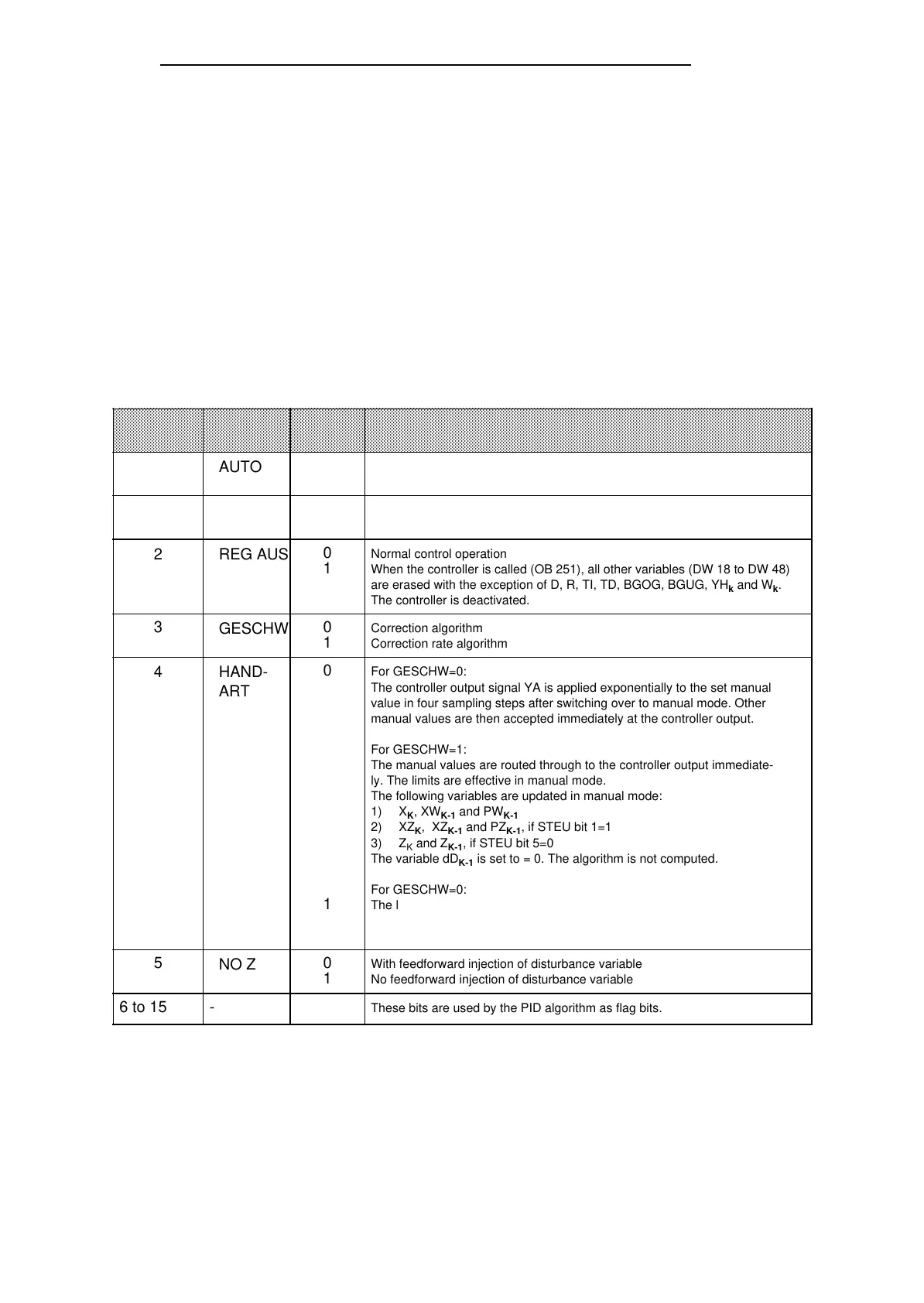
Table 6-2. Meaning of the Control Bits in Control Word STEU
NameControl
Bit
Signal
State
Meaning
0
0
1
Manual mode
Automatic mode
a
a
a
a
a
a
a
a
a
a
a
a
a
a
a
a
a
a
a
a
a
a
a
a
a
a
a
a
a
a
a
a
a
a
a
a
a
a
a
a
a
a
a
a
a
a
a
a
a
a
a
a
a
a
a
a
a
a
a
a
a
a
a
a
a
a
a
a
a
a
a
a
a
a
a
a
a
a
a
a
a
a
a
a
a
a
a
a
a
a
a
a
a
a
a
a
a
a
a
a
a
a
a
a
a
a
a
a
a
a
a
a
a
a
a
a
a
a
a
a
a
a
a
a
a
a
a
a
a
a
a
a
a
a
a
a
a
a
a
a
a
a
a
a
a
a
a
a
a
a
a
a
a
a
a
a
a
a
a
a
a
a
a
a
a
a
a
a
a
a
a
a
a
a
a
a
a
a
a
a
a
a
a
a
a
a
a
a
a
a
a
a
a
a
a
a
a
a
a
a
a
a
a
a
a
a
a
a
a
a
a
a
a
a
a
a
a
a
a
a
a
a
a
a
a
a
a
a
a
a
a
a
a
a
a
a
a
a
a
a
a
a
a
a
a
a
a
a
a
a
a
a
a
a
a
a
a
a
a
a
a
a
a
a
a
a
a
a
a
a
a
a
a
a
a
a
a
a
a
a
a
a
a
a
a
a
a
a
a
a
a
a
a
a
a
a
a
a
a
a
a
a
a
a
a
a
a
a
a
a
a
a
a
a
a
a
a
a
a
a
a
a
a
a
a
a
a
a
a
a
a
a
a
a
a
a
a
a
a
a
a
a
a
a
a
a
a
a
a
a
a
a
a
a
a
a
a
a
a
a
a
a
a
a
a
a
a
a
a
a
a
a
a
a
a
a
a
a
a
a
a
a
a
a
a
a
a
a
a
a
a
a
a
a
a
a
a
a
a
a
a
a
a
a
a
a
a
a
a
a
a
a
a
a
a
a
a
a
a
a
a
a
a
a
a
a
a
a
a
a
a
a
a
a
a
a
a
a
a
a
a
a
a
a
a
a
a
a
a
a
a
a
a
a
a
a
a
a
a
a
a
a
a
a
a
a
a
a
a
a
a
a
a
a
a
a
a
a
a
a
a
a
a
a
a
a
a
a
a
a
a
a
a
a
a
a
a
a
a
a
a
a
a
a
a
a
a
a
a
a
a
a
a
a
a
a
a
a
a
a
a
a
a
a
a
a
a
a
a
a
a
a
a
a
a
a
a
a
a
a
a
a
a
a
a
a
a
a
a
a
a
a
a
a
a
a
a
a
a
a
a
a
a
a
a
a
a
a
a
a
a
a
a
a
a
a
a
a
a
a
a
a
a
a
a
a
a
a
a
a
a
a
a
a
a
a
a
a
a
a
a
a
a
a
a
a
a
a
a
a
a
a
a
a
a
a
a
a
a
a
a
a
a
a
a
a
a
a
a
a
a
a
a
a
a
a
a
a
a
a
a
a
a
a
a
a
a
a
a
a
a
a
a
a
a
a
a
a
a
a
a
a
a
a
a
a
a
a
a
a
a
a
a
a
a
a
a
a
a
a
a
a
a
a
a
a
a
a
a
a
a
a
a
a
a
a
a
a
a
a
a
a
a
a
a
a
a
a
a
a
a
a
a
a
a
a
a
a
a
a
a
a
a
a
a
a
a
a
a
a
a
a
a
a
a
a
a
a
a
a
a
a
a
a
a
a
a
a
a
a
a
a
a
a
a
a
a
a
a
a
a
a
a
a
a
a
a
a
a
a
a
a
a
a
a
a
a
a
a
a
a
a
a
a
a
a
a
a
a
a
a
a
a
a
a
a
a
a
a
a
a
a
a
a
a
a
a
a
a
a
a
a
a
a
a
a
a
a
a
a
a
a
a
a
a
a
a
a
a
a
a
a
a
a
a
a
a
a
a
a
a
a
a
a
a
a
a
a
a
a
a
a
a
a
a
a
a
a
a
a
a
a
a
a
a
a
a
a
a
a
a
a
a
a
a
a
a
a
a
a
a
a
a
a
a
a
a
a
a
a
a
a
a
a
a
a
a
a
a
a
a
a
a
a
a
a
a
a
a
a
a
a
a
a
a
a
a
a
a
a
a
a
a
a
a
a
a
a
a
a
a
a
a
a
a
a
a
a
a
a
a
a
a
a
a
a
a
a
a
a
a
a
a
a
a
a
a
a
a
a
a
a
a
a
a
a
a
a
a
a
a
a
a
a
a
a
a
a
a
a
a
a
a
a
a
a
a
a
a
a
a
a
a
a
a
a
a
a
a
a
a
a
a
a
a
a
a
a
a
a
a
a
a
a
AUTO
Correction algorithm
Correction rate algorithm
3 0
1
GESCHW
Normal control operation
When the controller is called (OB 251), all other variables (DW 18 to DW 48)
are erased with the exception of D, R, TI, TD, BGOG, BGUG, YH
k
and W
k
.
The controller is deactivated.
2
0
1
REG AUS
5 0
1
With feedforward injection of disturbance variable
No feedforward injection of disturbance variable
NO Z
6 to 15 These bits are used by the PID algorithm as flag bits.-
4
0
1
HAND-
ART
For GESCHW=0:
The controller output signal YA is applied exponentially to the set manual
value in four sampling steps after switching over to manual mode. Other
manual values are then accepted immediately at the controller output.
For GESCHW=1:
The manual values are routed through to the controller output immediate-
ly. The limits are effective in manual mode.
The following variables are updated in manual mode:
1) X
K
, XW
K-1
and PW
K-1
2) XZ
K
, XZ
K-1
and PZ
K-1
, if STEU bit 1=1
3) Z
K
and Z
K-1
, if STEU bit 5=0
The variable dD
K-1
is set to = 0. The algorithm is not computed.
For GESCHW=0:
The last manipulated variable output is retained.
For GESCHW=1:
The correcting increment dY
K
is set to zero.
0
1
XW
k
is applied to the differentiator. No account is taken of the XZ input.
A variable other than XW
k
is applied to the differentiator via the XZ input.
XZ EIN1
The control program can be initialized with fixed values or parameters. Parameters are input via
the assigned data words. The controller is based on a PID algorithm. Its output signal can be either
a manipulated variable (correction algorithm) or a manipulated variable change (correction rate
algorithm).
6-16
EWA 4NEB 811 6149-02