Application S5-115F Manual
The following are implemented with this configuration
• Single-channel I/O modules
32 digital input modules, I/O type 1, address 32.0 to 35.7, subunit B, slot 2
32 digital output modules, I/O type 10, address 36.0 to 39.7, subunit B, slot 3
• Two-channel I/O modules
32 digital input modules, I/O type 3, address 0.0 to 3.7, subunit A+B, slot 0 with 32 check DQs
in subunit A, slot 2
16 digital output modules, I/O type 8, address 4.0 to 5.7, subunit A+B, slot 1 with readback DI
in subunit A+B
7.1.1 Installing and Wiring the Hardware
Secure both central racks
Plug the PS 951, the CPU and the digital modules into the central rack ( Figure 7-1).
Plug an IM 306 into the central rack of subunit A and set the addressing for subunit A.
Plug an IM 306 into the central rack of subunit B and set the addressing for subunit B.
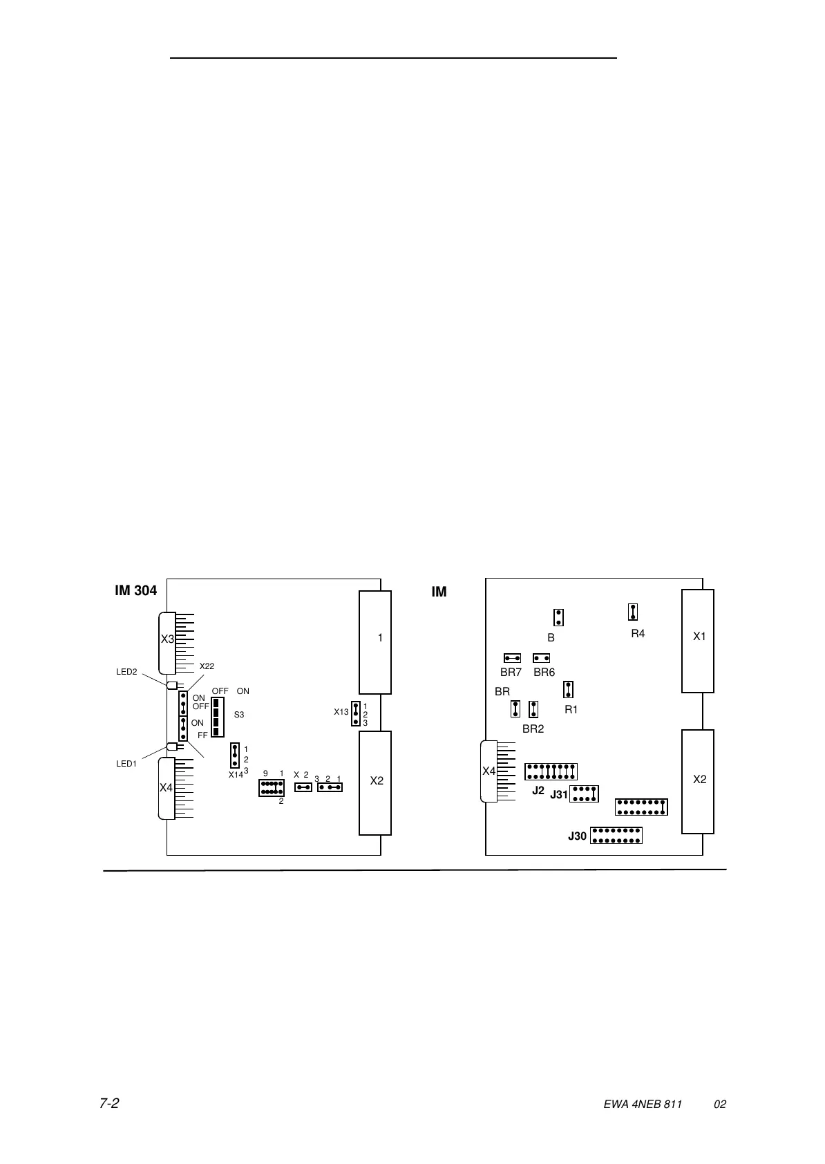
Check the settings for the parallel link on the IM 304 and IM 324 interface modules
( Figure 7-2)
Plug the interface modules with the adapter casings into slot 7 ( Figure 7-1)
Connect the IM 304 and IM 324 interface modules together with the 721 connecting cable.
Use the bottom connector on the IM 304 (connector X4)
Wire the I/O modules as shown in Figure 7-3.
Connect the PS 951F power supply.
Figure 7-2. Switch and Jumper Settings for Parallel Link
a
a
a
a
a
a
a
a
a
a
a
a
a
a
a
a
a
a
a
a
a
a
a
a
a
a
a
a
a
a
a
a
a
a
a
a
a
a
a
a
a
a
a
a
a
a
a
a
a
a
a
a
a
a
a
a
a
a
a
a
a
a
a
a
a
a
a
a
a
a
a
a
a
a
a
a
a
a
a
a
a
a
a
a
a
a
a
a
a
a
a
a
a
a
a
a
a
a
a
a
a
a
a
a
a
a
a
a
a
a
a
a
a
a
a
a
a
a
a
a
a
a
a
a
a
a
a
a
a
a
a
a
a
a
a
a
a
a
a
a
a
a
a
a
a
a
a
a
a
a
a
a
a
a
a
a
a
a
a
a
a
a
a
a
a
a
a
a
a
a
a
a
a
a
a
a
a
a
a
a
a
a
a
a
a
a
a
a
a
a
a
a
a
a
a
a
a
a
a
a
a
a
a
a
a
a
a
a
a
a
a
a
7-2
EWA 4NEB 811 6149-02