S5-115F Manual Application
7 Application
This section contains a simple example of an S5-115F in test mode. The I/O modules used include
the following:
• 32 reaction-free digital input modules, I/O type 1
• 32 failsafe digital input modules, I/O type 3
• 32 reaction-free digital output modules, I/O type 8
• 16 failsafe digital output modules, I/O type 10
The example contains, in a compact form, all the information necessary for mechanical installation
of the central controllers, wiring of I/O modules and configuration with COM 115F.
If required, the example can be expanded to suit all needs.
Hardware
You require the following for installing the S5-115F:
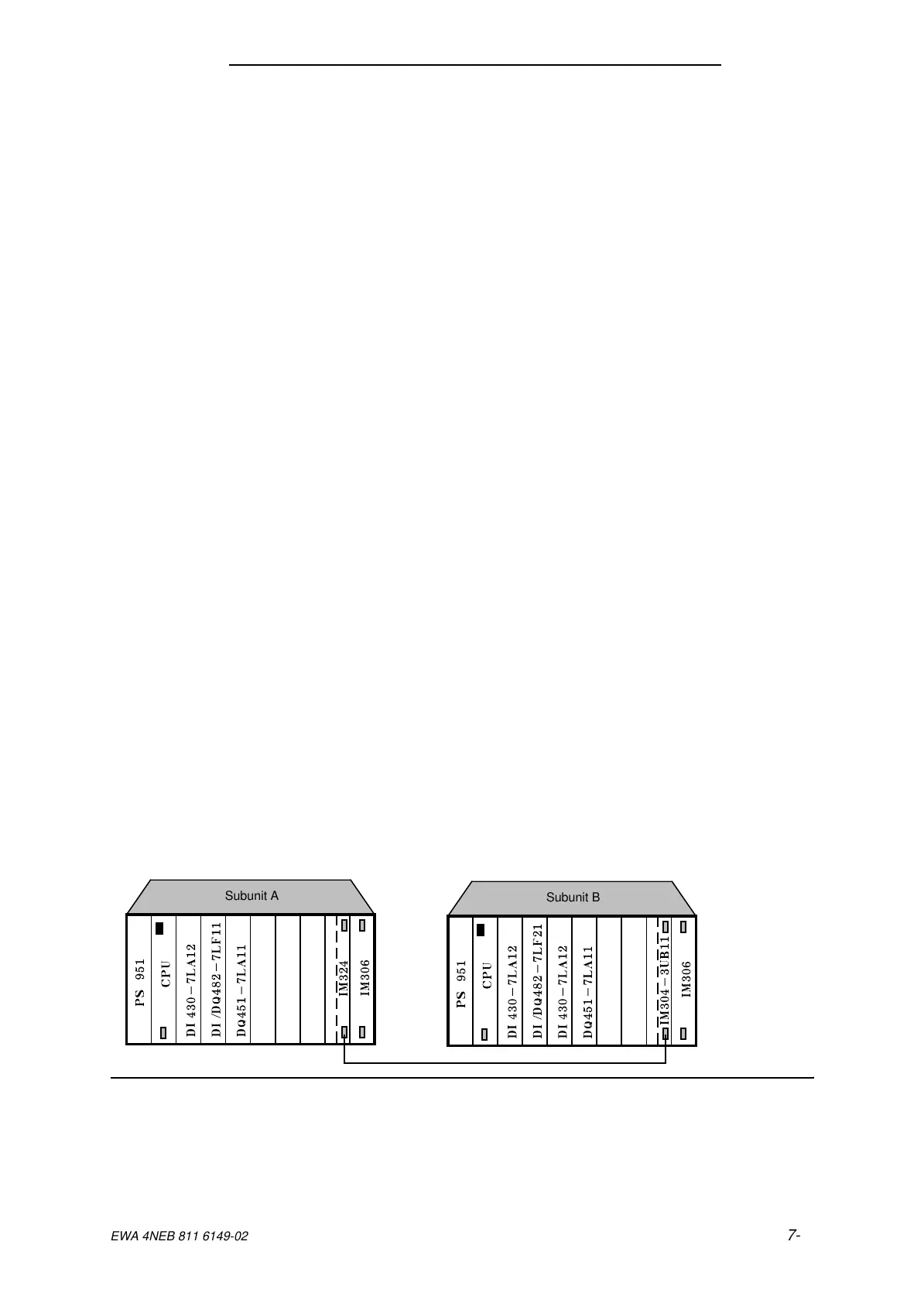
• 2 CR 700-2F subracks
• 2 CPU 942-7UF13 central processing units
• 2 PS 951 power supply units
• 2 DI 430-7LA12 digital input modules
• 1 DI/DQ 482-7LF11 digital input/output module
• 1 DI/DQ 482-7LF21 digital input/output module
• 1 DQ 451-7LA11 digital output module
• 1 IM 304-3UB11 interface module with adapter casing
• 1 IM 324-3UA12 interface module with adapter casing
• 1 721 connector cable
• 2 IM 306 interface modules
• 1 220V/24V power supply for the I/O modules
Software
You require
• The COM 115F software package, Version 3.0
• The STEP 5 basic package
7.1 Hardware Installation
Hardware installation and wiring of the I/O modules are described in this section.
Figure 7-1. System Configuration for the Application
a
a
a
a
a
a
a
a
a
a
a
a
a
a
a
a
Subunit A
a
a
a
a
a
a
a
a
a
a
a
a
a
a
a
a
Subunit B
EWA 4NEB 811 6149-02
7-1