S5-115F Manual Blocks
6.2 OB 251 PID Algorithm
The operating sytem of the CPU 942F has a PID algorithm which the user can apply to his needs
with the help of the OB 251 organization block.
Before calling OB 251, you must open a data block (PID DB) which contains the PID parameters and
other controller-specific data. The PID algorithm is called in a specific time grid (sampling interval)
and generates a manipulated variable. The greater the accuracy of the sampling interval, the more
accurately the controller can perform its tasks. The PID control parameters specified in the PID DB
must be adapted to the sampling interval.
Time-controlled processing is generally implemented with the time-interrupt OB (OB 13).
Organization block OB 13 can be programmed in call intervals of 10 ms to 10 min. Execution of the
PID control algorithm can take up to 1.7 ms.
Auto
1
dY
Y
°
STEU BIT 1
1
1
°
YH (STEU BIT 3 to 0)
dYH(STEU BIT 3 to 1)
Z
XW
UG
OG
0
1
0
°
1
0
PID
algorithm
°
W
X
XZ
YA (STEU BIT 3 to 0)
dYA (STEU BIT 3 to 1)
BGOG BGUG
K R TI TD
0
STEU BIT 3
STEU BIT 5
STEU BIT 0
STEU
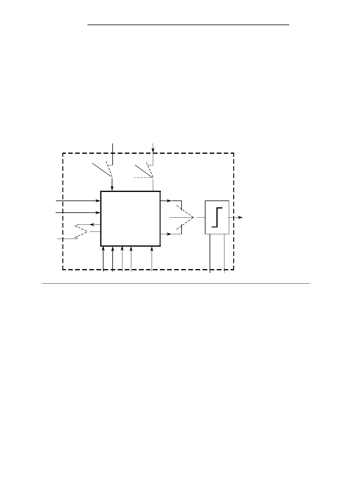
Figure 6-4. Block Diagram of the PID Controller
Legend:
K = Proportional action coefficient STEU = Control word
K>0 positive control direction Y = Manipulated variable
K<0 negative control direction dY = Correcting increment
R = R parameter (usually 1000) YH = Value for manual input
TA = Sampling interval dYH = Correcting increment for manual input
TN = Integral-action time BGOG = Upper limit
TV = Derivative-action time BGUG = Lower limit
TI = TA/TN X = Actual value input
TD = TV/TA Z = Disturbance variable
W = Setpoint XZ = Substitute variable for control deviation
XW = Control deviation YA = Controller output:
Manipulated variable limited
dYA = Controller output:
Correcting increment limited
The continuous-action controller is designed for controlled systems involving pressure, tem-
perature, or flow rate control.
The “R” parameter sets the proportional-action component of the PID controller.
If proportional action is required, most controller designs use the value R=1.
EWA 4NEB 811 6149-02
6-15