Blocks S5-115F Manual
Assigning Parameters to the PID Algorithm
The controller DB is OB 251's interface to its environment.
All data required for calculating the next value is stored in the controller DB. Every controller
requires its own controller DB.
Controller-specific data parameters are set in a data block, which must include at least 49 data
words.
If no DB is open or if the DB is not long enough, the CPU will stop with a transfer error (TRAF).
!
Important
Make sure the relevant controller DB has been opened before calling the OB 251
control algorithm. There must be no safety-related data in the controller DB. Opening
a DB with safety-related data can lead to dangerous states since OB 251 has only been
accepted as a ”reaction-free” block and not as a ”failsafe” block.
The inspector checks the call of the controller DB during the acceptance test.
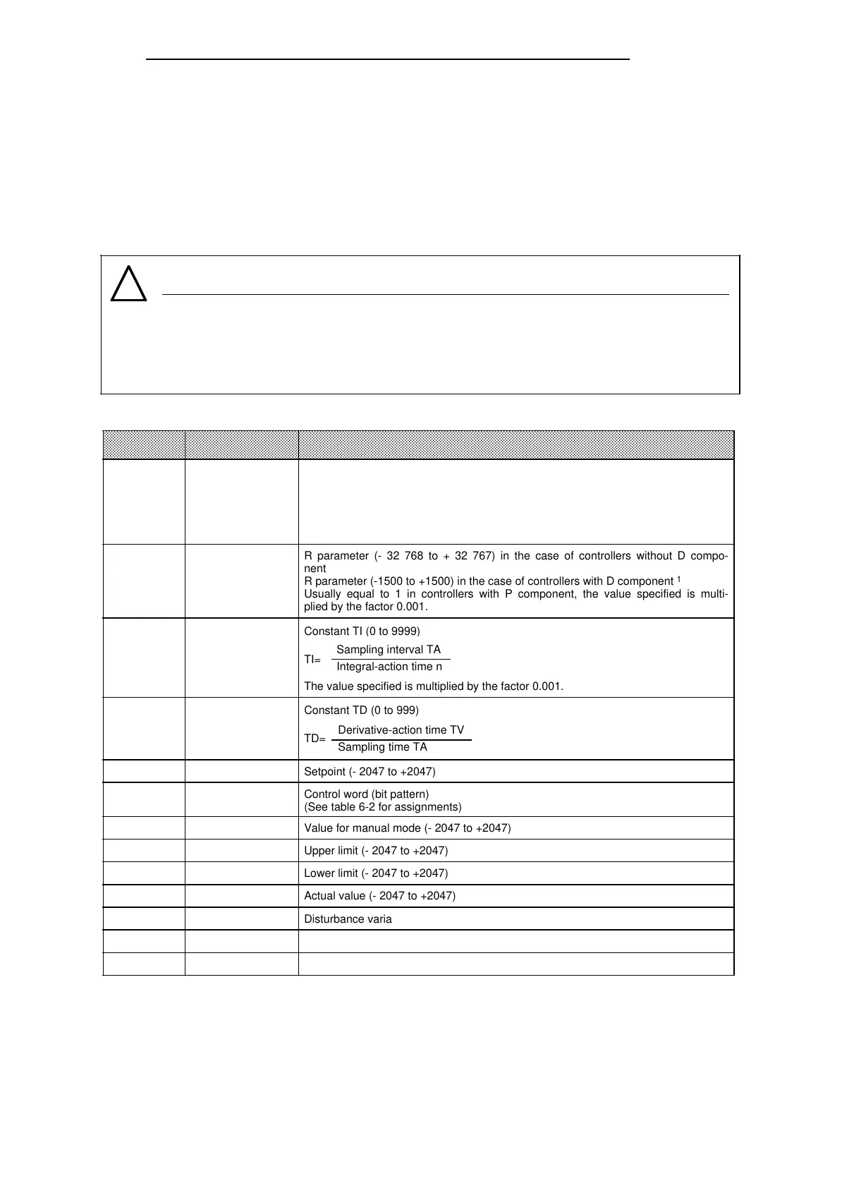
Table 6-3. Structure of the Data Transfer Block
1 Greater amplifications are possible if jump-like changes in the control difference are sufficiently small. Large changes of
the control difference should therefore be divided into several small changes; e.g. by applying the setpoint over a ramp
function.
Data Word Name Remarks
1
3
5
7
9
11
12
14
16
22
24
29
48
K
R
TI
TD
W
STEU
YH
BGOG
BGUG
X
Z
XZ
YA
Proportional action coefficient (-32 768 to +32 767) in the case of controllers
without D component
Proportional action coefficient (-1500 to +1500) in the case of controllers with D
component
1
K is greater than zero in positive control direction and less than zero in negative
control direction; the value specified is multiplied by the factor 0.001.
a
a
a
a
a
a
a
a
a
a
a
a
a
a
a
a
a
a
a
a
a
a
a
a
a
a
a
a
a
a
a
a
a
a
a
a
a
a
a
a
a
a
a
a
a
a
a
a
a
a
a
a
a
a
a
a
a
a
a
a
a
a
a
a
a
a
a
a
a
a
a
a
a
a
a
a
a
a
a
a
a
a
a
a
a
a
a
a
a
a
a
a
a
a
a
a
a
a
a
a
a
a
a
a
a
a
a
a
a
a
a
a
a
a
a
a
a
a
a
a
a
a
a
a
a
a
a
a
a
a
a
a
a
a
a
a
a
a
a
a
a
a
a
a
a
a
a
a
a
a
a
a
a
a
a
a
a
a
a
a
a
a
a
a
a
a
a
a
a
a
a
a
a
a
a
a
a
a
a
a
a
a
a
a
a
a
a
a
a
a
a
a
a
a
a
a
a
a
a
a
a
a
a
a
a
a
a
a
a
a
a
a
a
a
a
a
a
a
a
a
a
a
a
a
a
a
a
a
a
a
a
a
a
a
a
a
a
a
a
a
a
a
a
a
a
a
a
a
a
a
a
a
a
a
a
a
a
a
a
a
a
a
a
a
a
a
a
a
a
a
a
a
a
a
a
a
a
a
a
a
a
a
a
a
a
a
a
a
a
a
a
a
a
a
a
a
a
a
a
a
a
a
a
a
a
a
a
a
a
a
a
a
a
a
a
a
a
a
a
a
a
a
a
a
a
a
a
a
a
a
a
a
a
a
a
a
a
a
a
a
a
a
a
a
a
a
a
a
a
a
a
a
a
a
a
a
a
a
a
a
a
a
a
a
a
a
a
a
a
a
a
a
a
a
a
a
a
a
a
a
a
a
a
a
a
a
a
a
a
a
a
a
a
a
a
a
a
a
a
a
a
a
a
a
a
a
a
a
a
a
a
a
a
a
a
a
a
a
a
a
a
a
a
a
a
a
a
a
a
a
a
a
a
a
a
a
a
a
a
a
a
a
a
a
a
a
a
a
a
a
a
a
a
a
a
a
a
a
a
a
a
a
a
a
a
a
a
a
a
a
a
a
a
a
a
a
a
a
a
a
a
a
a
a
a
a
a
a
a
a
a
a
a
a
a
a
a
a
a
a
a
a
a
a
a
a
a
a
a
a
a
a
a
a
a
a
a
a
a
a
a
a
a
a
a
a
a
a
a
a
a
a
a
a
a
a
a
a
a
a
a
a
a
a
a
a
a
a
a
a
a
a
a
a
a
a
a
a
a
a
a
a
a
a
a
a
a
a
a
a
a
a
a
a
a
a
a
a
a
a
a
a
a
a
a
a
a
a
a
a
a
a
a
a
a
a
a
a
a
a
a
a
a
a
a
a
a
a
a
a
a
a
a
a
a
a
a
a
a
a
a
a
a
a
a
a
a
a
a
a
a
a
a
a
a
a
a
a
a
a
a
a
a
a
a
a
a
a
a
a
a
a
a
a
a
a
a
a
a
a
a
a
a
a
a
a
a
a
a
a
a
a
R parameter (- 32 768 to + 32 767) in the case of controllers without D compo-
nent
R parameter (-1500 to +1500) in the case of controllers with D component
1
Usually equal to 1 in controllers with P component, the value specified is multi-
plied by the factor 0.001.
Constant TI (0 to 9999)
TI=
The value specified is multiplied by the factor 0.001.
Sampling interval TA
Integral-action time n
Constant TD (0 to 999)
TD=
Derivative-action time TV
Sampling time TA
Setpoint (- 2047 to +2047)
Control word (bit pattern)
(See table 6-2 for assignments)
Value for manual mode (- 2047 to +2047)
Upper limit (- 2047 to +2047)
Lower limit (- 2047 to +2047)
Actual value (- 2047 to +2047)
Disturbance variable (- 2047 to +2047)
Applied D component (- 2047 to +2047)
Output variable (- 2047 to +2047)
All parameters (with the exception of the control word STEU) must be specified as 16-bit fixed-
point numbers.
6-18
EWA 4NEB 811 6149-02