Blocks S5-115F Manual
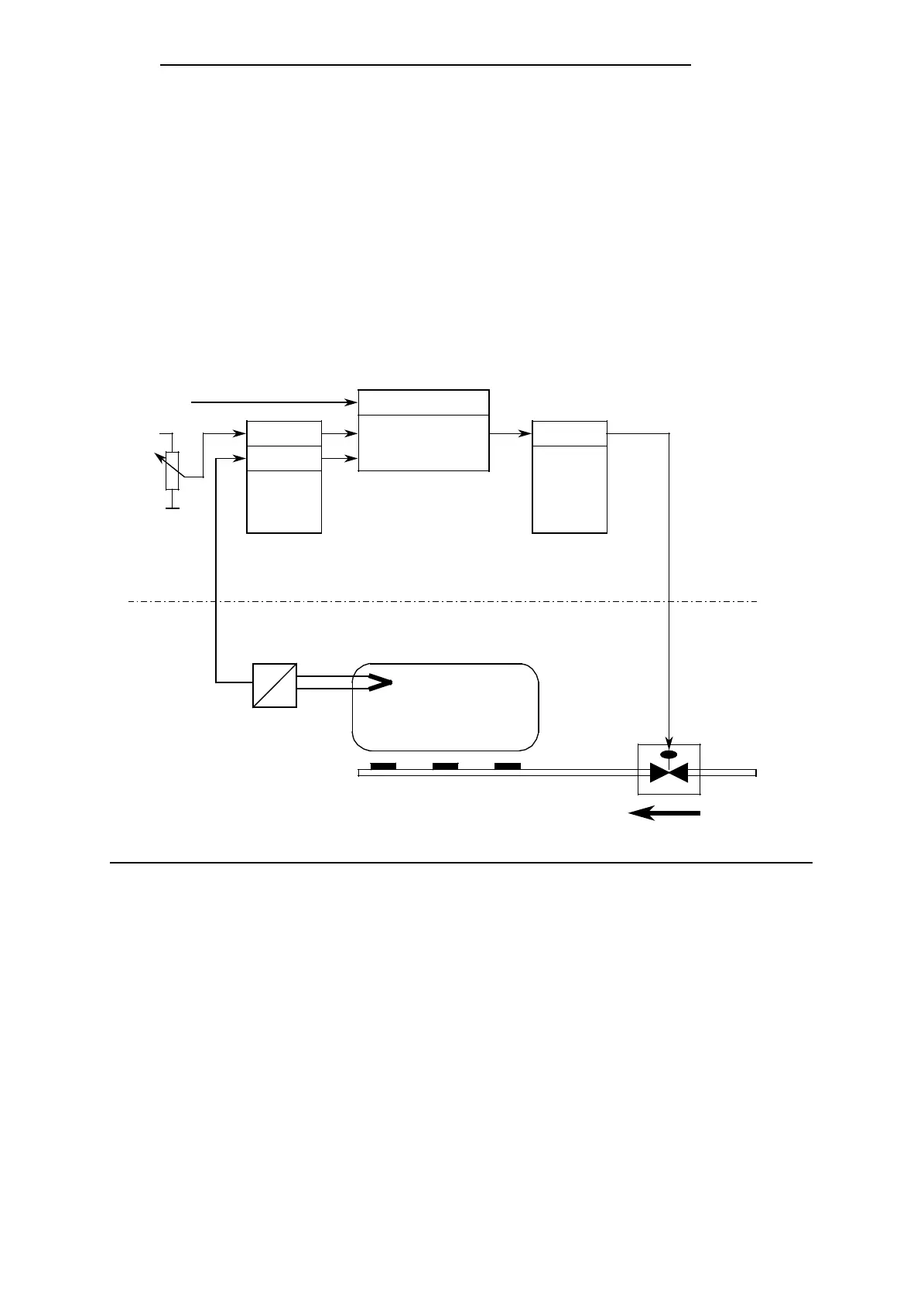
Typical application of the PID control algorithm in the S5-115F
A furnace is to be maintained at a constant temperature by a PID controller.
The temperature setpoint is entered by a potentiometer.
The setpoints and actual values reach the controller via an analog input module. The calculated
manipulated variable is then output via an analog output module. Neither the analog modules
nor the controller itself are safety-related.
The operating mode of the controller is set in input byte 0 (see control word DW 11 in the con-
troller DB).
The controller setting must be calculated for each controlled system by the usual controller design
method.
Temperatur sensor
Manipulated variable
Transducer
Actual value
Setpoint setter
Analog input module
(e.g. 6ES5 460)
OB 251 with
controller DB
(call in OB 13)
Y
Analog output module
(e.g. 6ES5 470)
=
=
W
X
+
Furnace
Channel 1
Channel 0
Control byte (DR 11)
EB0
PID control
algorithm
Channel 0
Actuator
Hot gas flow
Controlled
system
S5-115F
Figure 6-5. Process Schematic
The analog signals of the setpoints and actual values are converted into their corresponding
digital values at each sampling instant (determined by time OB 13). From this, OB 251 calculates
the new manipulated variable from which a corresponding analog signal will be generated with
the analog output. This signal is then applied to the controlled system.
6-20
EWA 4NEB 811 6149-02