Installation, connecting up, commissioning
3.2 Installing, connecting up and commissioning
CP 1243-8 IRC
Operating Instructions, 02/2018, C79000-G8976-C385-03
53
Table 3- 2 Procedure for installation and connecting up
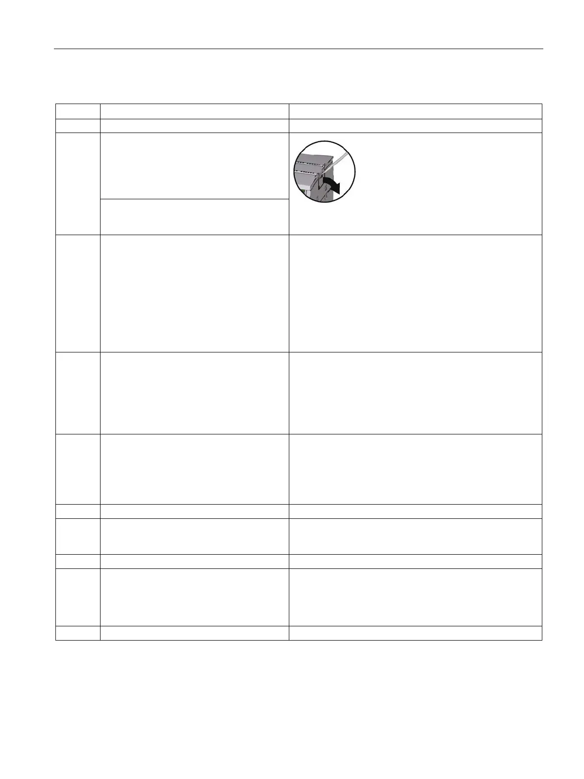
Remove the cover on the left-hand side of the
CPU.
1. Insert the tip of a slotted screwdriver in the
gap above the cover.
2. Lever the cover carefully from its holder.
Recommendation: Store the covers in a safe place for possible
later use.
When using a TS module: Remove the cover
on the left-hand side of the CP as described
Connect the CPU and CP and - if used - the
TS module.
Push to modules carefully together until the
side contacts are completely closed between
the two modules.
Permitted slots:
• CPU: Right:
• CP: In the middle (to the left of the CPU)
For the CP only one slot to the left beside the CPU is per-
mitted. Only one CP 1243-8 can be inserted.
• TS module: Left (to the left of the CP)
To the left of the CP 1243-8 IRC only a TS module can be
Connecting the power supply
• Secure the power supply wires to the
power output of the CPU.
• Secure the wires of the power supply to
the plug supplied with the CP and insert
the plug in the socket on the top of the CP.
The pinning of the power output of the CPU is printed on the
terminal on the top of the housing of the CPU, see /1/
(Page 225).
The pinning of the power input of the CP is printed on the top
of the housing of the CP beside the socket. You will also find
this in the section Pin assignment of the socket for the external
Connect the data cable to the CP:
• The Ethernet-cable when using Ethernet-
based communication.
• The relevant cable when using a TS mod-
ule.
You will find the pinout of the interface in the section Pinout of
the Ethernet interface (Page 185).
Close the front covers of the modules.
If the DIN rail clamps on the rear of the mod-
ules have been pulled out, push in all the DIN
rail clamps so that they are locked in place.
Place the connected modules on the DIN rail.
Press the connected modules onto the DIN
rail until the lower DIN rail clamps have locked
in place.
If you install devices vertically in an environment with vibration
or if you use a TS module GSM, mount end retainers
(8WA1 808) on the rail to ensure that the devices remain con-
Turn on the power supply.

 Loading...


