3-14
Installing Series 505 System Hardware TI545/TI555 System Manual
Installing the TI545/TI555 CPU (continued)
Switch
2 selects Port 1 as, either a programming port, or a printer port; see
Figure 3-12 for port locations. This port uses a RS-232/RS-423 signaling
protocol and uses a RS-232 pinout arrangement with a RS-423 (+5 V) signal
level extending up to 50 feet. A modem may be used to increase the cable
distance.
•
Setting Switch 2 to the left selects Port 1 as a programming port.
•
Setting Switch 2 to the right selects Port 1 as a printer port.
Selection between RS-232/RS423 or RS-422/RS-485 is accomplished by
cabling. If RS-422/RS-485 cabling is used, then dipswitch 1 selects between
RS-422 and RS-485 (see Figure 3-1
1). The cable installation for RS-485 or
RS-422 can include a 120-ohm termination resistor across the signal
conductors at each end of the cable. The resistor provides a higher noise
immunity and better long-distance communication (see Figure 3-12).
•
RS-232/RS-423 connection for Operator Interface up to 50 feet.
•
RS-422/RS-485 connection to 3300 feet (1 km).
Switch 1 is used as follows:
•
When RS-232 or RS-422 cabling is used, set Switch 1 to the left.
•
When RS-485 cabling is used, set Switch 1 to to the right. RS-485 uses
a single twisted pair to transmit and receive data between the
programming device and the CPU. Multiple CPUs or multiple
programming devices (on this RS-485 link) are currently not supported
and should not be used.
Port
1
Port 2
Pin Signal
3
9
5
8
2
DO+
DI+
GND
DO–
DI–
Controller
Male 9-Pin D
Type
Port 2
(1)
RS-422 Port Pinouts
Pin Signal
3
8
5
TX/RX+
TX/RX–
GND
Controller
Male 9-Pin D
Type
Pin Signal
1
2
3
4
5
RSD
RCV
XMT
DTR
GND
Controller
Male 9-Pin D
Type
Port 1
RS-232 Port Pinouts
6 DSR
7RTS
8 CTS
Pin Signal
2
3
5
RCV
XMT
GND
Controller
Port 2
(1)
RS-232 Port Pinouts
Male 9-Pin D
Type
Port 2
(2)
RS-485 Port Pinouts
(1)
Dipswitch 1 is ON
(2) Dipswitch 1 is OFF
T
ermination resistors can be
used for higher noise immunity
and better long-distance
communication.
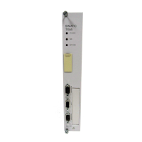
Figure 3-12 TI545/TI555
CPU Port Locations
Using Port 1
Using Port 2

 Loading...


