4-9
Cabling and Wiring the System
TI545/TI555 System Manual
4. Strip
back 1.50 in. (3.8 cm) of the sleeving on the other end of the cable.
5.
Remove 0.13 in. (0.33 cm) of each color
-coded insulation to expose the
bare wires.
6.
Install each wire end onto a terminal lug according to directions
provided by the vendor
.
NOTE:
The size of the terminal lug depends on the type of terminal block
used. Consult your vendor for the appropriate terminal lug size.
Use the following procedure to connect a drop line cable between the
programmable controller and terminal block.
1.
Ensure that the cable has been prepared as described on page 4-8.
2.
Plug the cable D-connector onto the CPU I/O connector
.
3. T
ighten two cable connector screws to secure the cable D-connector to
the CPU I/O connector
.
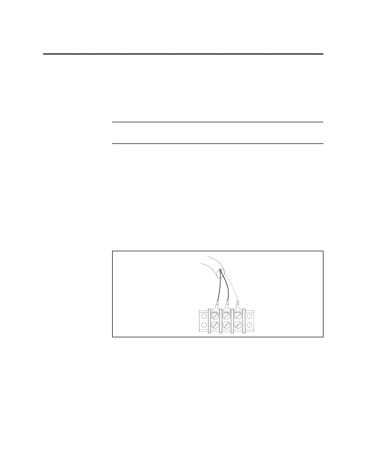
4.
Loosen three terminal screws on the terminal block and install the
cable lug terminals onto the terminal block. See Figure 4-4.
From
TI545/TI555
Figure 4-4 Connecting
to T
er
minal Block
5. T
ighten terminal block screws.
Connecting a CPU
Dr
op Line