Cabling and Wiring the System
4-8
TI545/TI555 System Manual
Installing Remote I/O Cables (continued)
Use
the following procedures to prepare drop line cables to connect the
programmable controller and RBC to terminal blocks:
1.
Strip back 1.50 inches (3.8 cm) of the sleeving on one end of the cable.
There are three wires when the sleeving is stripped back; two wires
have color coded insulation jackets and one is bare.
2.
Remove 0.13 in. (0.33 cm) of each color coded insulation jacket to
expose the bare wires.
NOTE:
One wire should already be bare.
3.
Install the cable wires to a 9-pin D-connector according to directions
provided by the connector vendor
.
NOTE:
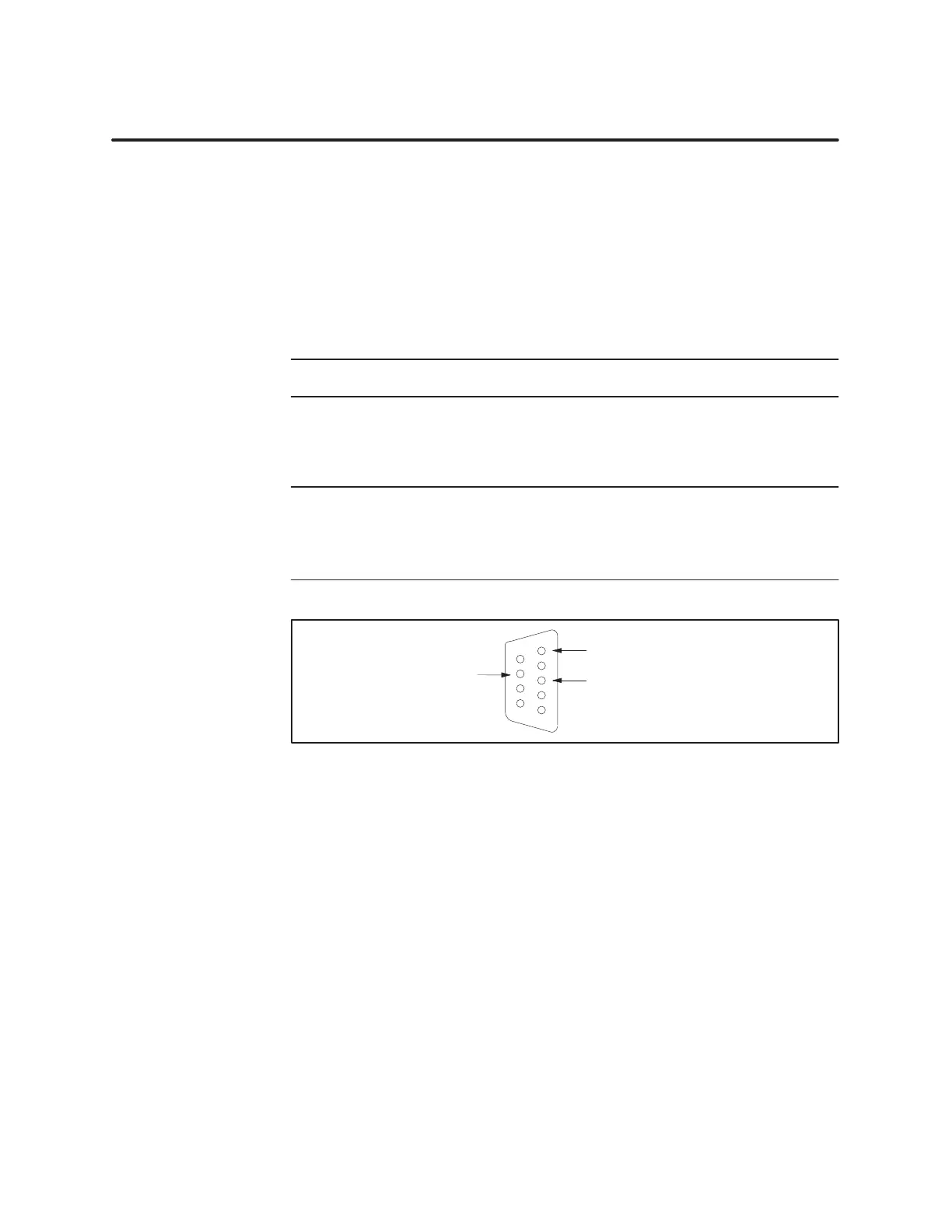
Install the wire without insulation to pin #5 of the 9-pin D-connector
.
Install the wires with the color
-coded insulation to pins #3 and #8.
It does not matter which wire is installed to pin #3 or #8, but all connectors
must be installed identically
. See Figure 4-3 for pin-out information.
Ground
(5)
Signal (3)
Signal (8)
6
1
9
5
Figure 4-3 9-Pin
I/O Female D-Connector Pinout
Pr
eparing Cables
(for Dr
op Lines)