Cabling and Wiring the System
4-14
TI545/TI555 System Manual
Installing Remote I/O Cables (continued)
Follow
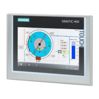
these guidelines when installing RS-485 trunk line cabling.
•
Measure the maximum length (listed in T
able 4-2) from the CPU to the
most distant tap. See Figure 4-7.
T T T
Maximum
T
runk Length
T = T
erminal Block
*A terminating resistor must be installed on the end terminal blocks. If only one terminal block is
used, a terminating resistor must be installed on that terminal block. See Figure 4-1
1 for details.
*Terminating
Resistor
T
*Terminating
Resistor
P
L
C
Figure 4-7 Maximum
T
runk Length
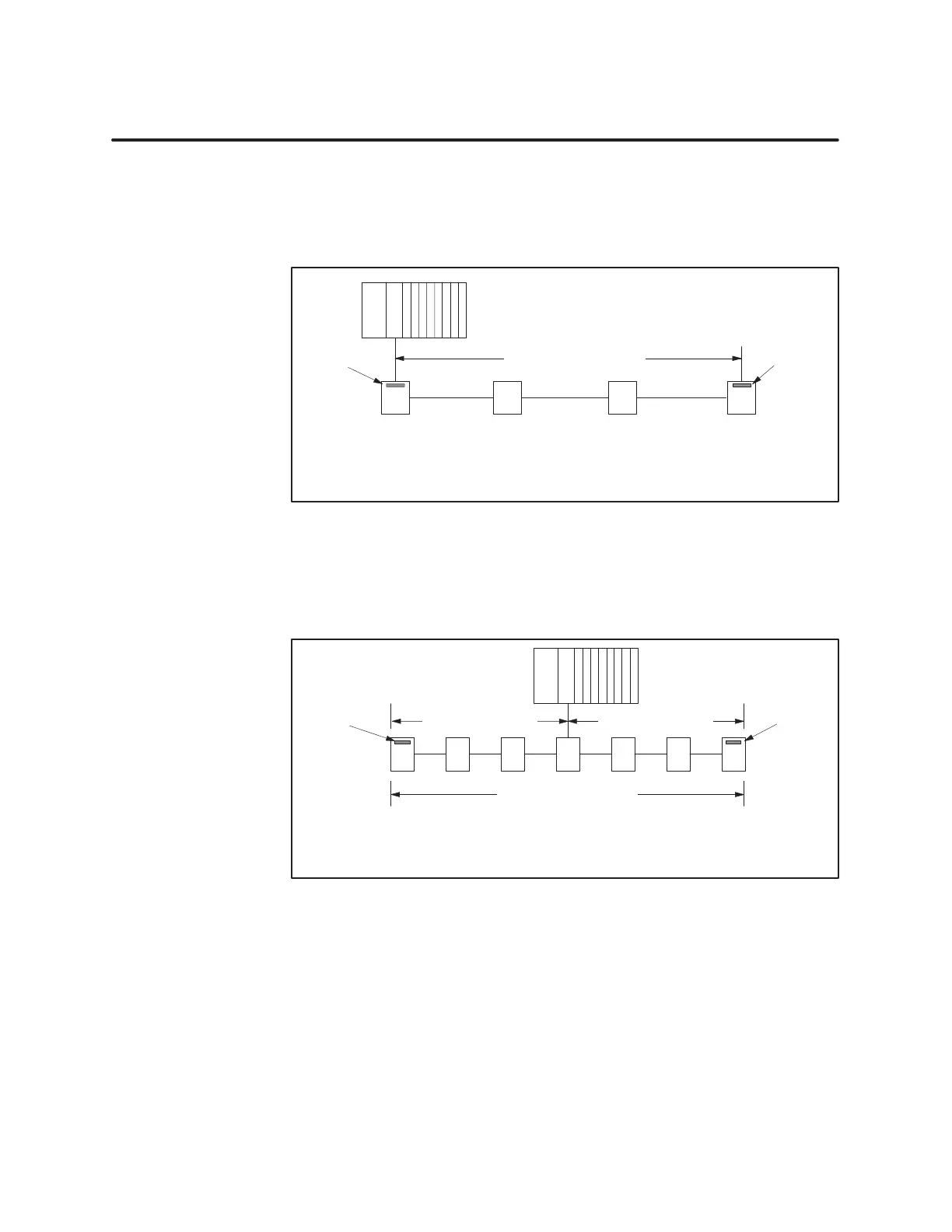
•
By using a T configuration (Figure 4-8), you can increase the total
trunk line length to twice the length specified in T
able 4-2.
T T
T
= T
erminal Block
T TTTT
T
otal T
runk Line Length
P
L
C
*A terminating resistor must be installed on the end terminal blocks. If only one terminal block is
used, a terminating resistor must be installed on that terminal block. See Figure 4-1
1 for details.
Max. T
runk Length
Max. T
runk Length
*Terminating
Resistor
*Terminating
Resistor
Figure 4-8 T
Configuration
•
Drop lines should be no longer than 10 m (33 feet).
•
Short drop lines of 1 m (3.3 feet) do not measurably affect signal quality
and do not have to be counted for the length reduction shown in
T
able 4-2.
Configuration
Requirements