Installing and connecting the device
3.5 Connecting the device
IFP V2, IFP V2 PRO, IFP V2 ETH
Operating Instructions, 03/2023, A5E46641410-AE
71
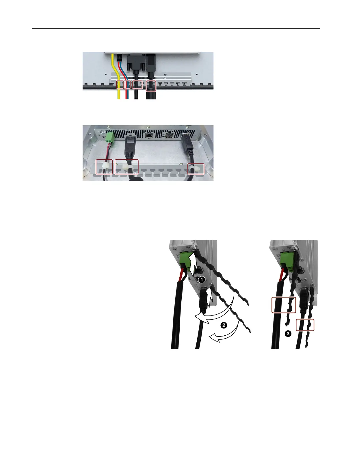
The following figure shows an example of securing the cables to the strain relief plate of a
PRO device.
3.5.7.2 Securing cables at the Transceiver Unit
The USB cable and the power supply cables connected to the Transceiver Unit must be
secured using the supplied strain relief elements.
To install the strain relief elements and secure the cables, proceed as follows:
Hang the strain relief elements
from the scope of delivery at
an angle of approx. 60° to the
vertical from below into the
corresponding opening in the
enclosure of the
Transceiver Unit.
Swivel the strain relief element
into the vertical position.
Secure the power supply
cables and the USB cable with
cable ties on the respective
strain relief element.
Make sure that the cables are
not crushed by the cable tie.
3.5.7.3 Securing cables for use in hazardous areas
Secure the IFP cables to the strain relief plate and the Transceiver Unit cables to the strain
relief elements as described in the previous section.