Technical information
7.2 Electromagnetic compatibility
IFP V2, IFP V2 PRO, IFP V2 ETH
92 Operating Instructions, 03/2023, A5E46641410-AE
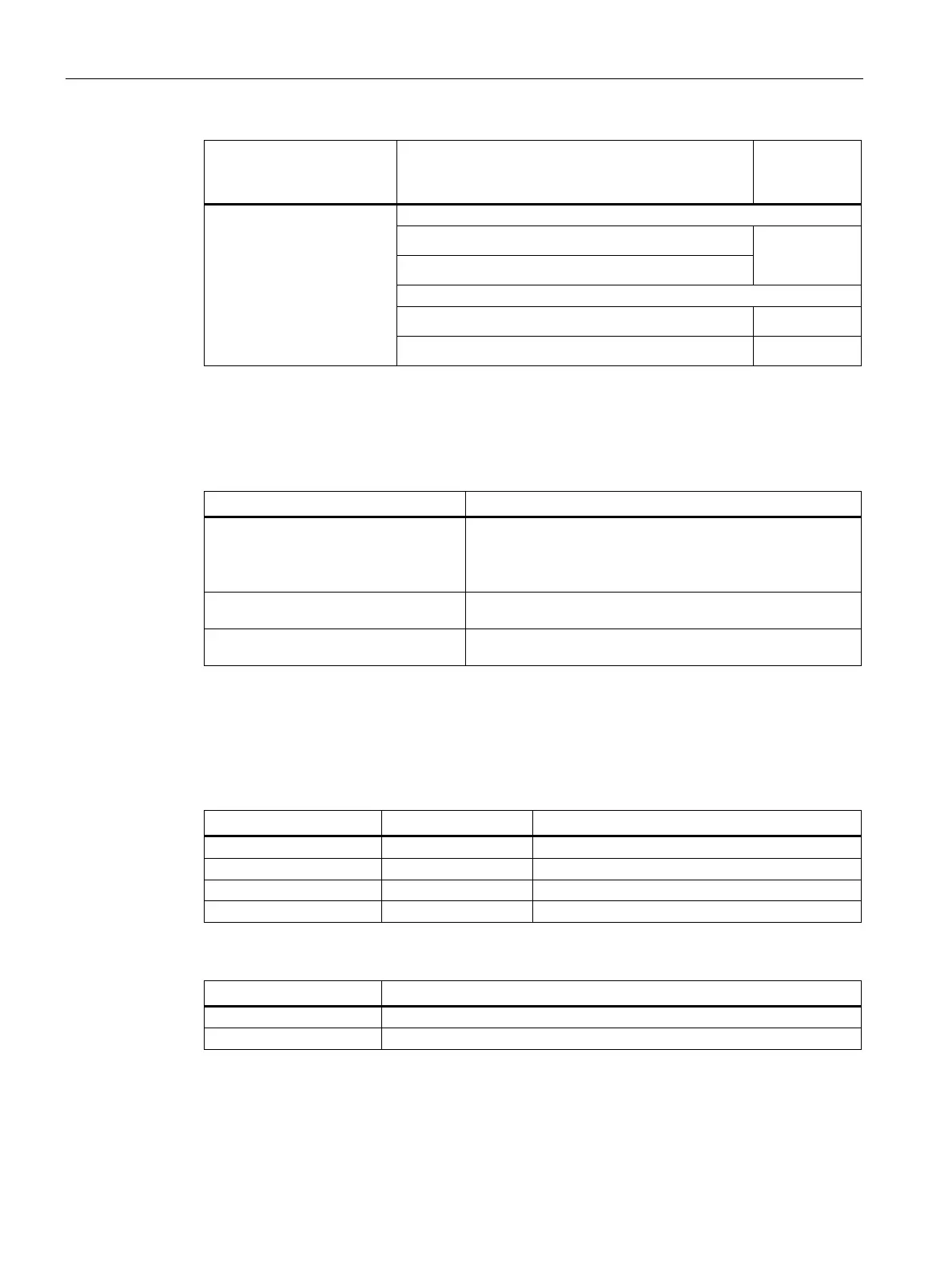
Pulse-shaped interference Tested with Performance
level equiva-
(surge) according to
IEC 61000-4-5
• 1 kV supply line, DC voltage
2
• 1 kV signal line/data cable, > 30 m
• 0.5 kV power cable, DC voltage
• 1 kV signal line, > 30 m,
3
Sinusoidal interference
The following table shows the EMC behavior of the modules with respect to sinusoidal
interference. This requires the device to meet the specifications and directives for electrical
installation.
HF radiation (electromagnetic fields)
according to IEC 61000-4-3
80% amplitude modulation at 1 kHz
• to 10 V/m from 80 MHz ... 1 GHz
• to 3 V/m from 1.4 ... 6 GHz
HF current feed on cables and cable
shields according to IEC 61000-4-6
Test voltage 10 V, with 80 % amplitude modulation of 1 kHz
in the 150 kHz ... 80 MHz range
Magnetic field strength according to
50/60 Hz; 30 A/m rms
Emission of radio interference
The following table shows the interference emission from electromagnetic fields according to
EN 61000-6-4, measured at the following distance.
Radiated emission (emitted interference)
< 40 dB (μV/m) quasi-peak
< 47 dB (μV/m) quasi-peak
< 76 dB peak and < 56 dB average
< 80 dB peak and < 60 dB average
Emission of radio interference voltages
< 79 dB quasi-peak and < 66 dB average
< 73 dB quasi-peak and < 60 dB average
See also
EMC information in section "Notes on use (Page 28)".