5 PLC Interface 10.94
5.3.13 DBs set-up for user (DB 66, 67, 68, 71)
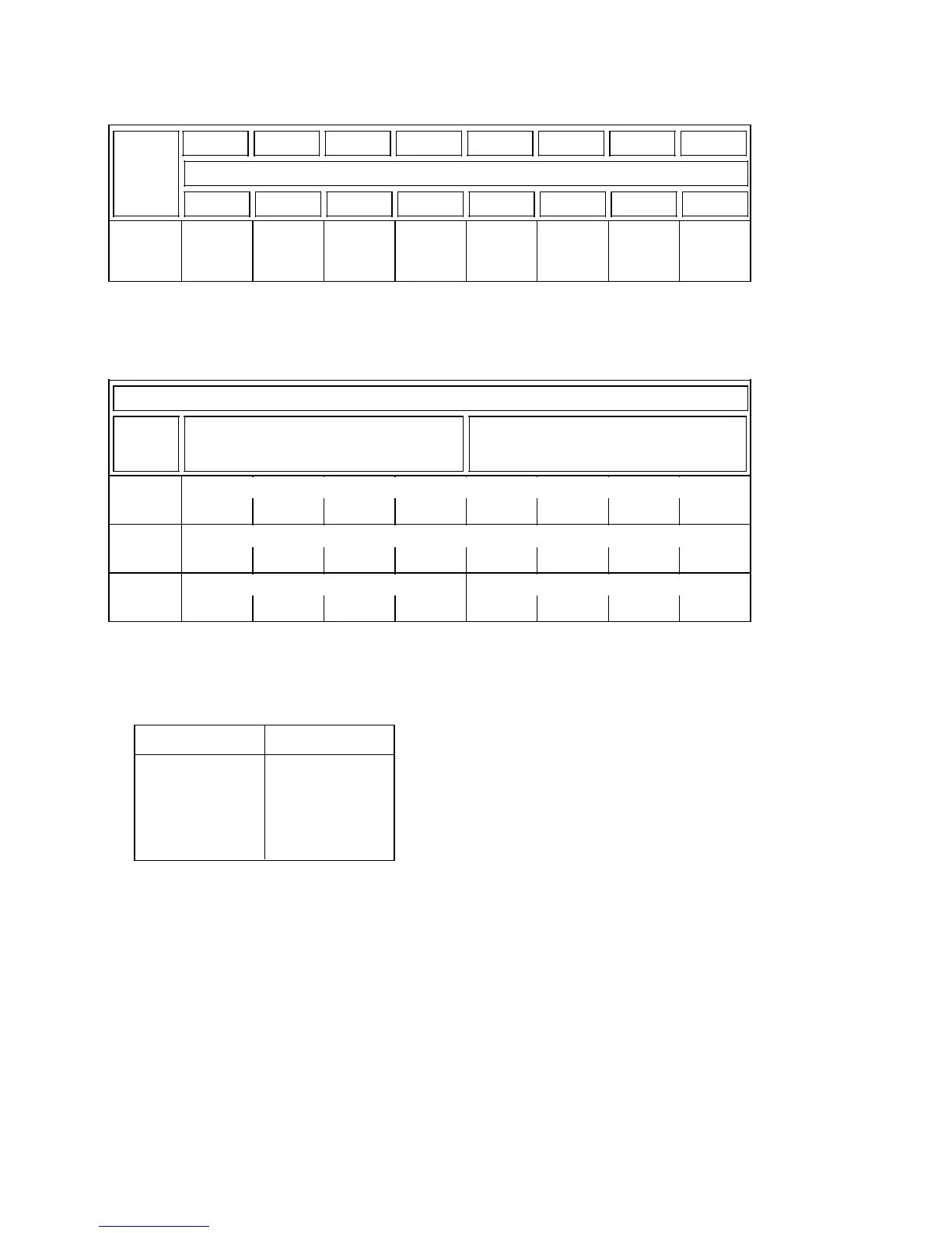
DB 71 for bits
7 6 5 4 3 2 1 0
Bit No.
Byte No.
PLC
DL 0
.
.
.
DR 15
15 14 13 12 11 10 9 8
5.3.14 Decoding lists for M signals (DB 80...DB 83)
1)
High byte (DL) Low byte (DR)
DW No.
PLC-
MD No.
DW
m+0
DW
m+1
DW
m+2
Decoding lists for M signals
Extended address
M address
Bit address, DW No. Bit address, bit No.
Notes:
• Address m is obtained from the following number of the M function definition:
M function m
1 0
2 3
3 6
.
.
.
.
.
.
64 189
• The table is to be completed consecutively from the first entry, gaps between entries are
not allowed. If less than 64 M functions are defined, unassigned entries are preset with 0.
All unassigned entries are located at the end of the table.
• The decoding lists are channel-specific, i. e. decoding list DB 80 is provided for NC
channel 1 and, accordingly, DB 83 is allocated to NC channel 4.
• M decoding according to the decoding list is activated channel-specifically via MDs.
_______
1) SW 4 and higher: DB 85
END OF SECTION
5–62
© Siemens AG 1992 All Rights Reserved 6FC5197- AA60
SINUMERIK 840C (IA)
 Loading...


